Continue to Site

Welcome to EDAboard.com

Welcome to our site! EDAboard.com is an international Electronics Discussion Forum focused on EDA software, circuits, schematics, books, theory, papers, asic, pld, 8051, DSP, Network, RF, Analog Design, PCB, Service Manuals... and a whole lot more! To participate you need to register. Registration is free. Click here to register now.

Charging circuit for two 3.7 V batteries that supply a 7.2 V device

Status
Not open for further replies.

jarce2000

Newbie level 2
Newbie level 2
Joined
Oct 29, 2008
Messages
2
Helped
0
Reputation
0
Reaction score
0
Trophy points
1,281
Visit site
Activity points
1,309
Two 3.7 V Li-ion batteries working in series supply power to a device that works at 7.4 V, but the batteries must be charged at 3.7 V. When an external charger is plugged in, the charging circuit is automatically activated to charge the batteries and the device stops working, when the charger is unplugged the device starts working by the power supplied by the batteries. Microcontrollers are not allowed.
I drew an outline of the circuit (see the attachment), but it needs to replace the switches by something that works automatically.
The device's circuit is in black, and the charging circuit is in red.
When the device is working the black switches are closed and the red switches are open.
When the batteries are charging, it happens the opposite: the black switches are open and the red switches are closed.

Regards
 

Attachments

  • Charging circuit outline.jpg
    Charging circuit outline.jpg
    45.5 KB · Views: 122

A "3.7V" Lithium battery cell is 4.2V when it is fully charged and is 3.2V when the load should be disconnected to prevent damage to the cell. Then the average voltage is 3.7V per cell.
 

Microcontrollers are not allowed.

why not? what is allowed?

most simple way is a relay, activated/powered by the charger, that turns off the device

Your first paragraph kinda contradicts the "When the .." statements
 

A "3.7V" Lithium battery cell is 4.2V when it is fully charged and is 3.2V when the load should be disconnected to prevent damage to the cell. Then the average voltage is 3.7V per cell.

That's not the point. The point is how to achive the goal (to begin to charge automatically when connected to a charger)

- - - Updated - - -

The simpler way is to connect all the switches in the outlined image to an single 8-pole slinding switch. But the point is to design an circuit that allows to charge automatically without any switch.

- - - Updated - - -

A "3.7V" Lithium battery cell is 4.2V when it is fully charged and is 3.2V when the load should be disconnected to prevent damage to the cell. Then the average voltage is 3.7V per cell.

That's not the point. The point is how to achive the goal (to begin to charge automatically when connected to a charger)
 

That's not the point.
The point is that your teacher is asking you to blow up a lithium battery that is already half-charged by charging it more and without using a balanced charger circuit.

Since your teacher also wants the load to be disconnected when the battery is charging then it is simple to detect that the current direction is for charging, not discharging, that activates your Mosfet or transistor switches.
 

The simplest way is to use a single battery with a boost converter like this to get 7.4V
**broken link removed**
 

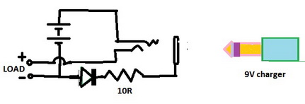
Charger need to be a regulate 9V supply such as from a 7809 regulator IC. 0.6V drop on diode is lessened from it and battery receive 8.4V through current limiting resistor. Voltage is divided by cells. 4.2V is on each cell. Cells need to be of same type and capacity. Charging current is kept reduced by resistor giving a margin but it can't be left connected for ever. A Chinese style simple solution.:thinker:
 

I have cheap Chinese chargers for the two-cells "7.4V" Li-Po batteries for my RC model airplanes. The batteries have 3-wires with the 3rd wire connected between the two cells so that the charger charges each cell separately (a balanced charger). The cells in the batteries are "identical" but might become a little different so the balanced charging circuit is used to prevent a fire if a cell is overcharged. Each cell is charged to exactly 4.20V and the charger disconnects when the charging current drops to a low amount.
 

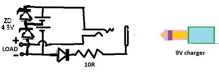
Two 1W 4.3V zener diodes can provide this protection.
Zener diodes with 5% tolerance are common. Then a Lithium cell is charged to only 4.085V which is too low or charged to 4.515 which is too high and might cause a fire.
Another fire hazard is caused when the cells are continuously over-charged.
 

Use one of these. Much simpler and safer


**broken link removed**
 
Last edited:

Status
Not open for further replies.

Part and Inventory Search

Welcome to EDABoard.com

Sponsor

Back
Top