neazoi
Advanced Member level 6
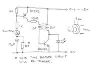
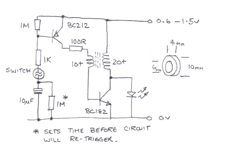
Here's my Mk3 version.
Using the same UV LED (Vf = 3.3V) it gives a bright flash at 0.9V supply with a 'just works reliably' supply voltage of 0.65V. I tried it up to 1.5V but not higher, it should be OK up to about 2V before the LED starts to draw it's own current.
I salvaged the ferrite core from a broken CFL, it seems to be used quite commonly in many different types but I do not have it's specifications or part number. You can get a slight increase in brightness by adding a 100nF capacitor from the junction of the 100R resistor and transformer to ground but it probably isn't worth fitting and it could risk the circuit self-biasing, in other words not shutting down after it has been triggered. It was OK for me but make sure it stops drawing current after a few seconds if you add it to your build. Increasing the 1M timing resistor will make it take longer to re-trigger but don't drop it below about 220K as it pass enough current to turn the first transistor on whenever the switch is closed.
Brian.
That is a different concept from the previous circuit isn't it?
As far as I understand it, the BC212 is turned ON, only when the vibraswitch is closed but only if the 10uF is mostly charged.
This means that a few vibrations are needed before the led can flash, assuming an initially discharged capacitor.
Have I understood that right? I think I am missing something here.
The other thing I am affraid of, is the joule thief efficiency. Would it draw more power than we want to save, because of it's bad efficiency compared to the capacitor charge pump?
Last edited:
")