Continue to Site

Welcome to EDAboard.com

Welcome to our site! EDAboard.com is an international Electronics Discussion Forum focused on EDA software, circuits, schematics, books, theory, papers, asic, pld, 8051, DSP, Network, RF, Analog Design, PCB, Service Manuals... and a whole lot more! To participate you need to register. Registration is free. Click here to register now.

change hysteresis in schmitt trigger circiut

Status
Not open for further replies.

Zeinabenaz

Newbie level 5
Newbie level 5
Joined
Jul 19, 2017
Messages
8
Helped
0
Reputation
0
Reaction score
0
Trophy points
1
Activity points
66
hi
someone can help me to analysis this circuit?
when Rpot is 1k and I start to reduce pot value the relay change condition((ON)) when Rpot= 275ohm and when I increase Rpot relay comeback unchange mode((off)) in 500ohm ,this operation it's okay to me but if I put Rpot = 470 ohm and start to reduce the Rpot the relay is on mode :-:)?: why???
and why does designer put Re2,Rb1,Rb2 ??? when I pick up Re2 my hysteresis change??
Capture.PNG
 

Hi,

is this for learning or did you really build it?
Wha not using a simple comparator?

***
Your circuit and the threshod depends on supply voltage. This is not given.
The thresholds depend on almost every single resistor value (more or less)

Changing the total value of Rpot won´t change the thresholds. You will always get the thresholds at 275/500 Ohms.
But for sure when your OFF threshold is at 500 Ohms, and your Rpot is only 470 Ohms .. you will never reach the 500 Ohms threshold. --> it will stay ON.

Imagine you have a trunk with 2m in length... and you want to build a bridge across a stream that is 2.50m wide....

Klaus
 
IMG_20170906_115603.jpg
hi
I think I could not say my question correctly
my supply voltage is 14v
when I reduce Rpot form 1k to zero my relay change state in Rpot=275 ohm and when increase Rpot form 275 to high relay is off in Rpot=500 ohm but when I reduce 470 ohm to low relay is ON , I think the diode is ON -->Q1 off -->relay ON
so when I reduce Rpot form 1k to zero ,the relay must be ON in 470 ohm but relay on in 275 ohm,why??
I want this circuit have a hysteresis between 275 to 500 ohm ,
thanks
 

Hi,

Try to decrease R4. Don`t go below 1k.

Klaus
 

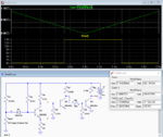
Below is the LTspice simulation of the modified circuit.
Changing R3 to 65Ω, R7 to 3.24kΩ and removing Re2 gave pot resistance trigger points of 500Ω and 282Ω.
(Note that the value for R1 is a non-standard resistor value.)

But, as has been noted, this is a complex circuit, with difficult to adjust threshold points, which could have been done very simply with a single comparator such as an LM339.

Capture.PNG
 
Last edited:

Hi,

Try to decrease R4. Don`t go below 1k.

Klaus

hi dear Klaus
I can not understand why you say I must change R4 value , this resistant value depend to UTP ?
 

Below is the LTspice simulation of the modified circuit.
Changing R3 to 65Ω, R7 to 3.24kΩ and removing Re2 gave pot resistance trigger points of 500Ω and 282Ω.
(Note that the value for R1 is a non-standard resistor value.)

But, as has been noted, this is a complex circuit, with difficult to adjust threshold points, which could have been done very simply with a single comparator such as an LM339.

View attachment 141014

hi
Please explain more about the reasons for the changes you gave?
thk
:)
 

Please explain more about the reasons for the changes you gave?

He could answer "due more simplicity" if the option is with discrete components, but I would ask istead: Could you exaplain why did you used the circuit you posted ?
 

Hi,

hi dear Klaus
I can not understand why you say I must change R4 value

Because R4 influences the hysteresis..

Klaus
 

He could answer "due more simplicity" if the option is with discrete components, but I would ask istead: Could you exaplain why did you used the circuit you posted ?

Hi
I use this circuit for detection a sensor .my sensor is like a variable resistor
but I'm not designer of this circuit ,I must solve just this problem and it is a attractive for myself why I have this problem
I hope to solve the problem instead of change the design

thanks for your collaboration
 

hi
Please explain more about the reasons for the changes you gave?
thk
:)
I made to changes based upon my understanding of the circuit and which resistors affected both the hysteresis and trigger points (there are several interacting resistors, which makes the design difficult to analyze).
I then adjusted those in the simulation until I got the results shown.
I did not do a formal analysis of the circuit.
 

Status
Not open for further replies.

Part and Inventory Search

Welcome to EDABoard.com

Sponsor

Back
Top