Continue to Site

Welcome to EDAboard.com

Welcome to our site! EDAboard.com is an international Electronics Discussion Forum focused on EDA software, circuits, schematics, books, theory, papers, asic, pld, 8051, DSP, Network, RF, Analog Design, PCB, Service Manuals... and a whole lot more! To participate you need to register. Registration is free. Click here to register now.

cavity stabilized oscilator functionality question

yefj

Advanced Member level 4
Joined
Sep 12, 2019
Messages
1,196
Helped
1
Reputation
2
Reaction score
3
Trophy points
38
Activity points
7,224
Hello, there is a schematic sof a cavity stabilised oscilator shown bellow, taken from the attached article.
first we have our YIG source which producin a 10GHZ signal with noise around it.
It gets amplified and put into a cavity resonator which produce a pure signal at 10GHZ.
I cant understand the logical part of the feedback:
we have a return signal going back ,we kill the signal using the reference signal using amplifier and phase shifter?
Why do wi kill the return signal if we want a feedback ?
We should save it to compare it with the original.
Thanks.
1685610711276.png
 

Attachments

  • High_spectral_purity_microwave_oscillator_design_using_conventional_air-dielectric_cavity.pdf
    563.8 KB · Views: 70
By suppressing the carrier, the double-balanced mixer (DBM) or phase detector (PD) when tuned to 90 deg offset, can measure baseband phase noise as shown. Cable lengths must be balanced. This phase error is used to control the capacitance on the air cavity resonator with a microwave diode (varactor or varicap diode)

There is no other carrier to lock to, so it just baseband negative feedback to improve the Q of the cavity.
 
Hello Mr.Stewart, I am having trouble to imagine this part of the explanantion.
We have a YIG signal which goes thre branch 2 (phi 2) in the schematics.
also we have branch1 going into a coupler to supress the carrier of the cavity oscilator.
So into the phase dector we get two signals :
1 .YIG with phase shift of phi2 in 90 degrees
2.the other is the cavity resonator signal with supressed carrier
So we have YIG signal(with carrier) shifted by 90 degrees compared with non shifted supressed carrier cavity resonator.
Could you please help me understand what is the logic of such comparisson?
why its letting use baseband phase noise measurement?
Thanks.

"By suppressing the carrier, the double-balanced mixer (DBM) or phase detector (PD) when tuned to 90 deg offset, can measure baseband phase noise as shown."
--- Updated ---

Update:
Why if we shift one signal by 90 degress then its idial base band phase noise?
 
Last edited:
The mixer has an output voltage for +/90 deg input differential and thus is best centred at 90 deg offset with carrier suppressed.

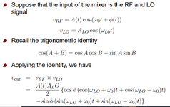
Do you understand the Fourier properties of a frequency mixer like the DBM for 2f and ∆φ?
 
Hello Mr.Stewart,could you please give me a mathematical expression which i could learn from and understand whats happening with the signals?
Thanks.
--- Updated ---

UPDATE:
We have our noisy YIG source (f0+noise) it gets into two routes :
1. going into the cavity oscilator producing pure f0
2.shifted by 90 degrees, so (f0+noise)+90 degree shift

we supress the main tone returned pure signal froms oscilator

So as i see it we have inside our phase detector two signals:
1.returned cavity oscilator signal with supressed carried(so basicly noise)
2.original YIG source (f0+noise) with 90 degree shift
What result do we expect? we compare pure noise to f0+noise with a shift.
they are totally different .
I cant see the physical logic in this comparison.
Thanks.
 
Last edited:
UPDATE 2:
Hello Mr.Stewart, Could you please help me simulate this effect.
I have a double balance mixer.
What input should i give it and what output should i expect so i could see this effect?
Thanks.
 
Last edited:
Hello Mr.Stewart, what kind of varactor do you reccomend to use for this purpose?
How to plug the varactor to the YIG source in order to change the frequency of the resonance of the cavity?
Thanks.
By suppressing the carrier, the double-balanced mixer (DBM) or phase detector (PD) when tuned to 90 deg offset, can measure baseband phase noise as shown. Cable lengths must be balanced. This phase error is used to control the capacitance on the air cavity resonator with a microwave diode (varactor or varicap diode)

There is no other carrier to lock to, so it just baseband negative feedback to improve the Q of the cavity.
 
Hello Mr.Stewart,a simulation of a phase detector using mixer is shown bellow by the theory shown bellow.
two tones at 10 GHZ with phase shift of 90 degrees.
A circuit and simulation plots is shown bellow.
cos(90)=0 V

As you can see both of my inputs have the same amplitude.
In our original curcuit, both inputs dont have the same tone amplitude.
What is the purpose of supressing tone amplitude on one input of the DBM phase detector?
The DBM will work perfectly fine when both tones have the same amplitude.
Thanks.
1686336063034.png


1686335187021.png

1686335711770.png


1686335667021.png
 

Attachments

  • 1686336812538.png
    1686336812538.png
    104.5 KB · Views: 61
Last edited:
you do not use a varactor in a yig oscillator.
in high quality yig oscillators there is a coarse tune coil, where you tune the oscillator to roughly 10 GHz. then there is a second fine tune coil that may exert another +/- 5 MHz of tuning. sometimes it is called a FM coil.
THAT is the coil you want to use in such a control loop. it has a modest frequency/voltage slope, so it does not pick up noise. AND the coil has much fewer turns, so it is not very inductive, and your control loop can handle it up to maybe 5 MHz of control loop bandwidth before it freaks out.

If i were you, i would disconnect the carrier nulling part (as it has its own issues to deal with) and just mix the direct reflection from that resonator in the phase detecting mixer. get THAT to work first. then away you go. Only if the measured phase noise is not good enough would i go back to carrier nulling at the phase detector.

Also, you do not need to take your output power from that Q=59,000 resonator. Unless you have some ultra low phase noise needs at say 1 MHz offset, taking the power off in between those two amplifiers would be fine. If the load varies on the output of the resonator, it effectively pulls the frequency of resonance, and the YIG will follow....resulting in degraded phase noise due to load variation. Either add a bunch of 10 GHz ferrite isolators, or do not use that as the output point
 
Hello biff44, What is the logic in the article for one sided carrier nulling?
As you can see on one input of the DBM we have regular carrier while in the other they did carrier nulling.
What is the logic in that?
Thanks.
 

LaTeX Commands Quick-Menu:

Part and Inventory Search

Welcome to EDABoard.com

Sponsor

Back
Top