Continue to Site

Welcome to EDAboard.com

Welcome to our site! EDAboard.com is an international Electronics Discussion Forum focused on EDA software, circuits, schematics, books, theory, papers, asic, pld, 8051, DSP, Network, RF, Analog Design, PCB, Service Manuals... and a whole lot more! To participate you need to register. Registration is free. Click here to register now.

[SOLVED] Capacitors connected to NMOS- Current and voltage characteristics

Status
Not open for further replies.

iVenky

Advanced Member level 2
Joined
Jul 11, 2011
Messages
584
Helped
37
Reputation
76
Reaction score
35
Trophy points
1,318
Location
College Station, Texas
Activity points
6,124
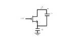
I have attached the circuit. The initial voltages across the capacitors C1 and C2 are +3V and +1V respectively. Ix and Vx are the currents and voltages that I would like to plot with time.
(Note that Vx is the voltage with respect to the ground.)


I tried it using LTSpice and I want to make sure if I am correct.

So could you please tell me the answer.

Thanks in advance.
 

Attachments

  • CMOSassessdoubt.png
    CMOSassessdoubt.png
    8.4 KB · Views: 140

The voltage across C2 does not change at all( the current can not flow through it). Therefore the Vgs=1 which means that the transistor always has over drive voltage( assuming that Vth<1).

t=0--> Vx=1+3=4Volts. trnasistor is in saturation and Vx drops linearly till transistor goes to triode Vx=1+2-Vth. After some time Vx reaches 1Volts and stayes constant.
 
  • Like
Reactions: iVenky

    iVenky

    Points: 2
    Helpful Answer Positive Rating
Status
Not open for further replies.

Similar threads

Part and Inventory Search

Welcome to EDABoard.com

Sponsor

Back
Top