Continue to Site

Welcome to EDAboard.com

Welcome to our site! EDAboard.com is an international Electronics Discussion Forum focused on EDA software, circuits, schematics, books, theory, papers, asic, pld, 8051, DSP, Network, RF, Analog Design, PCB, Service Manuals... and a whole lot more! To participate you need to register. Registration is free. Click here to register now.

Capacitor vs Varactor

Status
Not open for further replies.
Joined
Jan 22, 2022
Messages
2
Helped
0
Reputation
0
Reaction score
0
Trophy points
1
Activity points
32
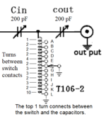
How can I replace a 50pf - 190pf variable capacitor with a varactor circuit that can handle about 100 watts? Have been searching everywhere for a solution.
This is for a home made antenna tuna I am building. As it stands right now it can only work with a small amount of voltage/watts.
 

Attachments

  • qrp-kit-antenna-tuner-erratum.png
    qrp-kit-antenna-tuner-erratum.png
    18 KB · Views: 145

Hi,

I don't think a capacitor and a varactor is specified for Watts at all.
--> calculate with Volts and Amperes.

Klaus
 

In theory, you could put many normal varactors in a series/parallel array (with DC blocking caps in between to allow the bias voltage to be distributed to each device). I toyed with such an idea for my own antenna tuner, but went for the standard approach of "fixed capacitors switched in by relays." Still wonder how the first idea would have worked out though, likely could have been more compact and definitely would require less DC power.
 

The RF voltage across the capacitor must be small compared to the control voltage, otherwise you dynamically change capacitance within each cycle of the RF voltage and create nonlinear distortion.

I would consider switched capacitor banks, to avoid this difficulty.
 

Many years ago power varactors were used in power frequency multipliers.
At that time, using a power varactor diode I made a 5W output power tripler from VHF frequencies up to UHF frequencies. I used MA4060 varactor which needs 12W input power to get about 6W output.


Working as power frequency multipliers, power varactor diodes have very high efficiency, better than any other silicon device (about 85% as doublers and about 55% as triplers).

Myself, I never seen a 100W varactor, but this guy claim a varactor working at 1kW:
 

Thank you everyone for your help! The information provided has been great and now I have some new ideas to play with. The Chinese build these things ATU's which are very small and cheap but would like to build my own. Maybe I will order one and see how they did it it may be a bit difficult since I am assuming everything will be surface mounted, but it is worth s try. I like the idea of tapped capacitor network though. Think they a few capacitors and tuned coils that might work and be interesting and fun to build.
Thanks again
George
Alberta, Canada
-12c a warm day!
03 Feb, 2022
 

I am not aware of any ATU using power varicaps.
The ATU used in old HF transceivers (>25 years ago) use small DC motors and mechanical variable capacitors.
All the new HF transceivers have ATUs using relays to switch a bunch of fixed capacitors and inductors.
 

as mentioned, varactors are DC voltage controlled.
so if you put 100 watts across one, odds are it will drastically change its operating point (and may blow up in a puff of smoke).

that said, IF you can find a varactor diode with a HUGE I region....and i mean mamouth, the RF sine wave impinging on it will not be positive long enough for electrons to conduct all the way across the I region and cause a short circuit in the diode. Not sure who would make such a diode, but a clue would be its huge breakdown voltage, like perhaps 1 Kv?

What you MIGHT do is put a number of varactors IN SERIES. Four varactor diodes in series would only see 1/4 of the RF voltage envelope. and since power is proportional to (V squared)/R, 1/4 the voltage means 1/16th the power disippated. Unfortunately, the capacitance also gets reduced by 1/4....

someone mentioned M/A-com diodes. they made an "ISIS" diode that was two diodes in series (with some elaborate diamond heat sinking to dissipate the power). it worked because you were halving the voltage to each of the two diodes inside of the package
 

The 100W is a problem for most switches. Maybe a (very) high
voltage PIN diode can tolerate the +40dBm through-power,
its control circuit is something you'd have to add.

PIN diodes, I consider "small signal" generally because you
pick up some distortion at higher powers, if your "on"
capacitance develops too much voltage-across, the junction
will add its nonlinearity. You might need an even higher rated
PIN diode (or parallel array, of?) for some "backoff".

Might suggest a parallel relay matrix for gross stepping and a
varactor in parallel with that, for the finest tuning. Or, just more
relay bits until you have the resolution you like. What is "good
enough" antenna match? That ought to set the LSB....
--- Updated ---

Another option - what about a mechanized-core inductor?
Like is commonly used in load-pull test benches? That might
be easier to hand-build.


A thing to consider, is that PIN diodes as tuning elements must operate small-signal to avoid much distortion, and as you reduce C you likely increase losses beyond what a switch application (operating at either max-C (high forward current) or min-C (high reverse voltage), but not between) will impose. There may be issues operating at high through-power in the "linear-C" region.

But shunt compensation elements can be scaled, paralleled to spread such a load. Still recommend a "mostly switched, with a little linear" approach so most of the PIN diodes are in well known / safe operating regimes
 

MSW2T-020522 PIN diode support 1kW (60dBm) in frequency range 20MHz to 520MHz.

There are many simple ATU on the net.interesting!@
One of the simplest and most used is this one:

You can buy the kit from here:
Interesting!
Notice that the data sheet specifies 1KW for COLD SWITCHING.
since this is a transmitter tuner application, where you switch in/out capacitor values as you watch the VSWR, it is likely being HOT SWITCHED (i.e. the tranmitter is ON while the PIN diodes are changing state). so you would have to derate that power handling number considerably.
 

In any high RF power switching (whatever is a relay or a solid-state switch) is recomended to place a delay turning the TX RF ON.
The TX RF should be turned ON after the switch is placed in the desire position.
In this way you don't have to derate anything.
 

Status
Not open for further replies.

Part and Inventory Search

Welcome to EDABoard.com

Sponsor

Back
Top