s.jayaram88
Junior Member level 1

- Joined
- May 25, 2012
- Messages
- 18
- Helped
- 1
- Reputation
- 2
- Reaction score
- 1
- Trophy points
- 1,283
- Location
- Bangalore, India
- Activity points
- 1,399
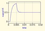
In qucs I rigged up a simple circuit which charges a capacitor and then discharges it. The capacitor charges fully but when discharging it does only to half i.e., if the capacitor was charged to 1 V, it discharges only to 0.5 V. Why is this?? Pls help me with an answer. this is the circuit.
<Qucs Schematic 0.0.16>
<Properties>
<View=0,0,901,800,1,0,0>
<Grid=10,10,1>
<DataSet=switch_rc.dat>
<DataDisplay=switch_rc.dpl>
<OpenDisplay=1>
<Script=switch_rc.m>
<RunScript=0>
<showFrame=0>
<FrameText0=Title>
<FrameText1=Drawn By:>
<FrameText2=Date:>
<FrameText3=Revision:>
</Properties>
<Symbol>
</Symbol>
<Components>
<Vdc V1 1 200 240 18 -26 0 1 "1 V" 1>
<Switch S1 1 330 170 -26 11 0 0 "off" 0 "1 ms" 0 "0" 0 "1e12" 0 "26.85" 0>
<GND * 1 410 350 0 0 0 0>
<R R2 1 410 280 15 -26 0 1 "1 kOhm" 1 "26.85" 0 "0.0" 0 "0.0" 0 "26.85" 0 "US" 0>
<R R1 1 250 170 -26 15 0 0 "1 kOhm" 1 "26.85" 0 "0.0" 0 "0.0" 0 "26.85" 0 "US" 0>
<Switch S2 1 410 210 11 -26 0 1 "off" 0 "5 ms" 0 "0" 0 "1e12" 0 "26.85" 0>
<C C1 1 520 250 17 -26 0 1 "1 uF" 1 "0" 1 "neutral" 0>
<.TR TR1 1 740 130 0 65 0 0 "lin" 1 "0" 1 "20 ms" 1 "1001" 0 "Trapezoidal" 0 "2" 0 "1 ns" 0 "1e-16" 0 "150" 0 "0.001" 0 "1 pA" 0 "1 uV" 0 "26.85" 0 "1e-3" 0 "1e-6" 0 "1" 0 "CroutLU" 0 "no" 0 "yes" 0 "0" 0>
</Components>
<Wires>
<200 170 200 210 "" 0 0 0 "">
<200 170 220 170 "" 0 0 0 "">
<280 170 300 170 "" 0 0 0 "">
<410 240 410 250 "" 0 0 0 "">
<520 280 520 310 "" 0 0 0 "">
<410 310 520 310 "" 0 0 0 "">
<200 270 200 310 "" 0 0 0 "">
<200 310 410 310 "" 0 0 0 "">
<410 310 410 350 "" 0 0 0 "">
<410 170 410 180 "" 0 0 0 "">
<360 170 410 170 "" 0 0 0 "">
<520 170 520 220 "" 0 0 0 "">
<410 170 520 170 "" 0 0 0 "">
<520 170 520 170 "oupput" 550 140 0 "">
</Wires>
<Diagrams>
</Diagrams>
<Paintings>
</Paintings>
And I have attached the snapshots too


