Aisha.Raj
Newbie level 3

- Joined
- Feb 16, 2013
- Messages
- 4
- Helped
- 0
- Reputation
- 0
- Reaction score
- 0
- Trophy points
- 1,281
- Activity points
- 1,354
PROBLEM STATEMENT
Without using a microcontroller or a dedicated timer IC, implement a circuit which, when a trigger is applied , will provide a +ve pulse of amplitude 3V, whose width can be varied from 0.1ms to 10s. You may not use any capacitor greater than 1uF or resistor larger than 470kohm. You are provided with op-amps which operate off + or – 10V. Provide a provision to continuously vary the duty cycle from 25% to 75%.
MY SOLUTION
Monostable multivibrator to provide positive one-shot pulses ( stable state is –Vcc) of amplitude +Vcc.
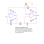
Pulse Width varied by varying R1C1 time constant . So I fixed R1 = 470kohm and varied C1 . But C1 cant take values greater than 1uF . So I want to use a capacitance multiplier to increase the value of capacitance and also this capacitance has to be varied so I will vary the gain(R7/R6) of the capacitance multiplier.
Duty cycle can be varied by varying the R2C2 time constant of the trigger circuit (which is basically a passive RC differentiator-high pass filter to which square waves of time period T>> R2C2/10 is fed by a function generator) . Here too I fixed R2 = 470kohm and varied C2 . Since very large and variable C2 values were required for this , I again want to use a variable gain capacitance multiplier as above.
So essentially I am using 2 different – variable gain capacitance multiplier whose capacitance value b/w i/p and o/p node is 1uF , and the amplified version of which is seen from the input side ( due to Miller’s Effect) given by the equation, Cin =C(1+R7/R6) where either R7 or R6 is a variable resistance.
Then at the o/p stage of the multivibrator , I put back to back zeners to clip the voltages to (Vz + Vf) and –(Vz to Vf) which roughly estimates to be +(3.3+1.1) and –(3.3+1.1) (ie) 4.4V to -4.4V. Zeners used have a forward drop of 1.1 V max and Vz = 3.3 V (1N5226) . This is further clipped by using a +ve clipper circuit of 2 pn- diodes (1n4001 of Vd =0.7V ) and a load resistor Rl = 10kohm .
The o/p of this entire design is taken from Rl (10kohm) .
MY PROBLEMS
1. I do not know how to connect the capacitance multipliers to my circuit such that , for one capacitance multiplier Cin appears as C1 and the other capacitance multiplier Cin appears as C2.
2. Will there be any effects due to frequency which’ll impede the working of my circuit as it should behave?? Because I remember that Miller effect has something to do with frequency. I ask this as to provide the required pulse width and duty cycle I may have to give the input to the trigger from few Hz to few MHz . So will the circuit function good for this ??
3. Also, at the clipper end I used a random value of Rl as 10kohm. Is there a specific way to choose this Rl value???
4. Any other problems I will face while simulating or implementing this circuit that you can see. Any errors in logic or design that you can detect???
I’d be really grateful if you could advice me suitably on the issues I raised . I have been given a deadline – 20th Feb 2013, gotta present the design to my panel on 21st . So I’d be extremely happy if we can figure out something by then ……Sorry for the extreme short notice and tks for your help in advance.
I am attaching the circuit with this post.

Without using a microcontroller or a dedicated timer IC, implement a circuit which, when a trigger is applied , will provide a +ve pulse of amplitude 3V, whose width can be varied from 0.1ms to 10s. You may not use any capacitor greater than 1uF or resistor larger than 470kohm. You are provided with op-amps which operate off + or – 10V. Provide a provision to continuously vary the duty cycle from 25% to 75%.
MY SOLUTION
Monostable multivibrator to provide positive one-shot pulses ( stable state is –Vcc) of amplitude +Vcc.
Pulse Width varied by varying R1C1 time constant . So I fixed R1 = 470kohm and varied C1 . But C1 cant take values greater than 1uF . So I want to use a capacitance multiplier to increase the value of capacitance and also this capacitance has to be varied so I will vary the gain(R7/R6) of the capacitance multiplier.
Duty cycle can be varied by varying the R2C2 time constant of the trigger circuit (which is basically a passive RC differentiator-high pass filter to which square waves of time period T>> R2C2/10 is fed by a function generator) . Here too I fixed R2 = 470kohm and varied C2 . Since very large and variable C2 values were required for this , I again want to use a variable gain capacitance multiplier as above.
So essentially I am using 2 different – variable gain capacitance multiplier whose capacitance value b/w i/p and o/p node is 1uF , and the amplified version of which is seen from the input side ( due to Miller’s Effect) given by the equation, Cin =C(1+R7/R6) where either R7 or R6 is a variable resistance.
Then at the o/p stage of the multivibrator , I put back to back zeners to clip the voltages to (Vz + Vf) and –(Vz to Vf) which roughly estimates to be +(3.3+1.1) and –(3.3+1.1) (ie) 4.4V to -4.4V. Zeners used have a forward drop of 1.1 V max and Vz = 3.3 V (1N5226) . This is further clipped by using a +ve clipper circuit of 2 pn- diodes (1n4001 of Vd =0.7V ) and a load resistor Rl = 10kohm .
The o/p of this entire design is taken from Rl (10kohm) .
MY PROBLEMS
1. I do not know how to connect the capacitance multipliers to my circuit such that , for one capacitance multiplier Cin appears as C1 and the other capacitance multiplier Cin appears as C2.
2. Will there be any effects due to frequency which’ll impede the working of my circuit as it should behave?? Because I remember that Miller effect has something to do with frequency. I ask this as to provide the required pulse width and duty cycle I may have to give the input to the trigger from few Hz to few MHz . So will the circuit function good for this ??
3. Also, at the clipper end I used a random value of Rl as 10kohm. Is there a specific way to choose this Rl value???
4. Any other problems I will face while simulating or implementing this circuit that you can see. Any errors in logic or design that you can detect???
I’d be really grateful if you could advice me suitably on the issues I raised . I have been given a deadline – 20th Feb 2013, gotta present the design to my panel on 21st . So I’d be extremely happy if we can figure out something by then ……Sorry for the extreme short notice and tks for your help in advance.
I am attaching the circuit with this post.