vsoumyavarma
Newbie level 3
Hi,
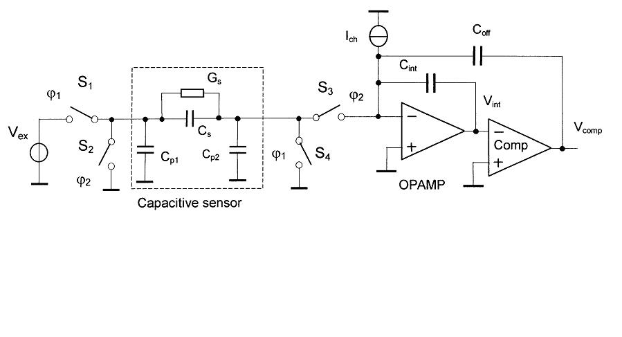
I am trying to simulate an interface circuit for capacitive sensors which is based on switched capacitor technique.
My problem is that while varying the sensor capacitor, the frequency is not varying.It is constant.But when there is a feedback from the comparator output to the sensor input, then there is frequency variation. But then what is the use of this input voltage source?
Also, it is mentioned that there is a controlled current source.But I don't know which voltage/current controls the source.