salova322
Newbie level 4
Hello, can you please explain the purpose of some parts of the circuit? Why are they needed and are they needed at all?
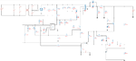
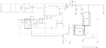
This circuit was generated on a Texas Instruments site. 12V 8A, uc3844a. Q1 is a 9 V stabilizer, but why they included it in the circuit, I saw 12 V circuits in which it does not. The circuit with a zener diode of 0.55 volts. I do not understand why it is here.
- - - Updated - - -
https://imgur.com/a/IWWg8