Continue to Site
Follow along with the video below to see how to install our site as a web app on your home screen.
Note: This feature may not be available in some browsers.


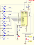
When the input pot resistance is turned down too low and the battery can supply plenty of current then the pot and/or the battery will blow up!Battery Tester Project Using LM3914 IC
is this circuit can be function well?
https://www.electronics-project-design.com/batterytester.html
Battery Tester Project Using LM3914 IC
is this circuit can be function well?
https://www.electronics-project-design.com/batterytester.html
When the input pot resistance is turned down too low and the battery can supply plenty of current then the pot and/or the battery will blow up!
Thank you for your answer, now my problem is don't know why the 18,17,16 pin LED will light up even no battery is testing.
I think the LED on pin 1 will also light with no battery on the input.Thank you for your answer, now my problem is don't know why the 18,17,16 pin LED will light up even no battery is testing.

I think the LED on pin 1 will also light with no battery on the input.
It is a stupid circuit, designed by somebody who does not understand the LM3914.
The LM3914 creates 1.25V between pin 7 and pin 8 just like an LM317 voltage regulator. The 1.25V across R1 causes a current of 1.25V/1k= 1.25mA. This 1.25mA also flows through the pot on the input of the circuit causing a voltage there that the LM3914 is showing.
I fixed the circuit for you: