Continue to Site

Welcome to EDAboard.com

Welcome to our site! EDAboard.com is an international Electronics Discussion Forum focused on EDA software, circuits, schematics, books, theory, papers, asic, pld, 8051, DSP, Network, RF, Analog Design, PCB, Service Manuals... and a whole lot more! To participate you need to register. Registration is free. Click here to register now.

Can I use IR2113 Low side Only!!

Status
Not open for further replies.

kioperapong

Newbie level 4
Joined
Sep 27, 2009
Messages
7
Helped
0
Reputation
0
Reaction score
0
Trophy points
1,281
Location
Thailand
Activity points
1,332
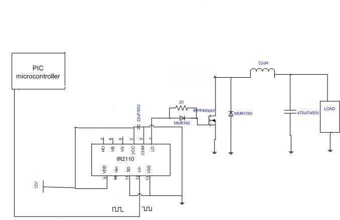
I try to connect Boost converter long time.

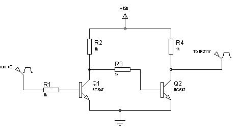
and i find the way to use IR2113 Low side only

When i connect it! OverLoad All time


Any One Could Help me,Plz

Thank
 

How about a circuit diagram and a clear problem description. "OverLoad All time" is somewhat vague, isn't it?
 

I can't build picture

I follow this picture all

But I don't connect pin10(Hin) pin7(Ho) and don't put upper mosfet

Pin2(Com) connect the G of mosfet

last pin5(Vs) don't conect the D of mosfet

Vin for Ir2113 12Vdc

Vin for My boost 12Vdc

When i On the Supply it's disconnect and overload alert

ps. sorry for the picture & my bad English (Ir2110 same the pin of Ir2113)

Thank
 

Pin2(Com) connect the G of mosfet
Really? Sounds bad.
Vin for My boost 12Vdc
A boost converter should have it's input at the load node (right side of the inductor). If this is the case in your circuit,
where is the output and the output diode?

You can use Windows Paint tool to sketch new and modify existing drawings. It's easy. E.g. like this:

62_1265664147.jpg
 

Hi,
You can't directly drive an IR2110 from a PIC. Instead interface it with transistors / logic level drivers (eg TC427).
Hope this helped.
Tahmid.
 

You mean ir2110 don't work with pic but i just use transistors / logic level drivers (eg TC427)

Could you draw diagram using transistors or tc 427?

And Don't have any way to use ir2110?

Thank
 

I mean, you can use only transistors/logic level drivers, or you can use these to interface with the IR2110.
Take a look here:
8_1264687893.jpg


Tahmid.
 

Connect follow your picture and connect it to ir2110

and when connect to ir2113 for low side only how?

Thank
 

Thank you Every Comment

Now it's work

I know Why it overload?

My supply For digital circuit
 

You can't directly drive an IR2110 from a PIC.
You can, by supplying 5V VDD to the chip.

Instead interface it with transistors / logic level drivers (eg TC427).
A TC427 actually can replace the IR2110 as a low side driver.
 

You can, by supplying 5V VDD to the chip.
According to Fig 12B in the IR2110 datasheet, when you apply 5v VDD, the input threshold voltage is ~4v. But the micrcontroller can not supply 4v with PWM. So, it should not work. And actually it will not work.
Tahmid.
 

But the micrcontroller can not supply 4v with PWM. So, it should not work. And actually it will not work.
Strong words! Your statement sounds like you have actually tried. But we both know, that you didn't.

What's actually said in the IR2110 datasheet? Fig. 12B is simply visualizing a standard CMOS input characteristic with 30%
and 70% thresholds. The specification is exactly identical to a standard CMOS logic device. Since when a PIC processor can't
drive standard CMOS levels?

Your statement seems also to suggest a different PIC output level specification in PWM mode. But PIC processors have only a
common output level specification for all digital outputs. The specification is valid for a load current. An unloaded output has
effectively Vdd output level. So you get about 1.5V guaranteed level margin, when supplying PIC and IR2110 with Vdd=5V.

It's a different question, if you should use a higher logic level in power electronics to achieve a better noise immunity.
 
Strong words! Your statement sounds like you have actually tried. But we both know, that you didn't.
Actually I did try it and what I said is from practical experience. That is why I have used transistor interface circuits between the microcontroller and IR2110.
Your statement seems also to suggest a different PIC output level specification in PWM mode.
I meant that in PWM, the voltage varies with duty cycle right, so, when I have 50% duty cycle, my voltage comes down to less than 2.5v, which is below the specified 4v requirement of the IR2110.
 

what I said is from practical experience.
There is likely another reason why it didn't work for you. It works by specification and also with the real part. I'm using IR2110
with 5V logic level in a product, it's operating reliably.

I meant that in PWM, the voltage varies with duty cycle right, so, when I have 50% duty cycle, my voltage comes down to less than 2.5v.
The average value varies, the logic level doesn't, it's always "L" < 0.4 V and "H" > 4.6 V, independant of the duty cycle.
 

Hi,

I tried a few times to interface PIC with IR2110 directly and it didn't work for me. For that reason, I use the transistor interface circuits.

In different forums also, I found that people could not interface their PICs to IR2110 directly. Maybe there was some other fault.
 

Hi FvM,
I've reconstructed a PWM circuit with ATmega88 and this time I see that it works with 5v as you mentioned. Thanks. I guess there was some other problem in my other circuits.
I just get a lot of noise from the circuit. I'll just see to that, could be other problems.
Thanks for the help.
 

Can i ask, is the signal at HO and LO of IR2113 a squarewave signal?
 

like i told you in your other tread you post the input signal does'nt matter it all depends on the type of output wave for m you want, eg if you want square wave output then you input square wave pulse but if you want pure sinewave output then you input sine pwm signal.
 
But what is the normal voltage for vdd supply,in some circute they used 3.3v why?while some used the same supply with it's vcc.
 

Status
Not open for further replies.

Part and Inventory Search

Welcome to EDABoard.com

Sponsor

Back
Top