Continue to Site

Welcome to EDAboard.com

Welcome to our site! EDAboard.com is an international Electronics Discussion Forum focused on EDA software, circuits, schematics, books, theory, papers, asic, pld, 8051, DSP, Network, RF, Analog Design, PCB, Service Manuals... and a whole lot more! To participate you need to register. Registration is free. Click here to register now.

calculation of change in zener voltage

Status
Not open for further replies.

Bhuvanesh123

Advanced Member level 4
Full Member level 1
Joined
Aug 29, 2013
Messages
113
Helped
0
Reputation
0
Reaction score
0
Trophy points
16
Location
Singrauli, India, India
Visit site
Activity points
814
i dont know how to do the calculation in the attached image.10 for dynamic resistance i dont know 0.1 and 0.01 are used plzz help.thank you in advance
 

Attachments

  • DSC_4727.jpg
    DSC_4727.jpg
    1.6 MB · Views: 125

The values 0.1 and 0.01 are from the text above the equation.

a zener might have a dynamic resistance of 10 ohms at 10mA, at its zener voltage of 5 volts. ...blah, blah...
we find that a 10% change in applied current....blah, blah...voltage of

deltaV = Rdyn deltaI = 10 x 0.1 x 0.01 =10mV

At least that's what it looks like to me.

Regards
 

A diode junction dynamically varies its own resistance, from megohms down to a fraction of an ohm.

That is a large dynamic range. The V-versus-A curve is exponential.

The textbook however deals only with a narrow range. In real circuits we need to be aware of a zener diode's response to a much larger range of current, anywhere from a micro-Amp to several Amps.

To get a grasp on the entire diode curve, it would help if you do some experimenting. Perform tests by sending different amounts of current through a real diode. Simultaneously read voltage across it. Graph the data.

This kind of learning process takes some work, but it was enlightening for me.
 

A diode junction dynamically varies its own resistance, from megohms down to a fraction of an ohm.
That is a large dynamic range. The V-versus-A curve is exponential.
Did you realize that we speak about a Zener diode?
 

In SPICE diode model, diode reverse current is an exponentional function of Vd+BV (Vd forward voltage, BV breakdown voltage) in contrast to the forward current, which is an exponential function of Vd. (Both with additional scaling factors).
 

In SPICE diode model, diode reverse current is an exponentional function of Vd+BV (Vd forward voltage, BV breakdown voltage) ......

Yes - I know. However, in this context, I like to make reference to a corresponding note from Berkeley University:
"The existing SPICE diode model cannot be used to accurately represent the I-V characteristic of a Zener diode in the reverse region."

(https://www.google.de/url?sa=t&rct=...zHfItLwd4gZ7Opw&bvm=bv.68911936,d.bGQ&cad=rja)
 
  • Like
Reactions: FvM

    FvM

    Points: 2
    Helpful Answer Positive Rating
Yes - I know. However, in this context, I like to make reference to a corresponding note from Berkeley University:
"The existing SPICE diode model cannot be used to accurately represent the I-V characteristic of a Zener diode in the reverse region."

(https://www.google.de/url?sa=t&rct=j&...,d.bGQ&cad=rja)
No doubt about. I wanted to remember that the breakdown I-V characteristic of diodes, also of zener diodes, is exponential in a first order, but different than stated in post #3. Although the SPICE diode model is inaccurate in breakdown region, it's generaly used for zener diode modelling. Also enhanced SPICE versions like HSPICE are mostly using the basic diode model for Z-diodes.
 
  • Like
Reactions: LvW

    LvW

    Points: 2
    Helpful Answer Positive Rating
Before Motorola changed their name to ON Semi then to whatever they call themselves today, they published a very detailed study of zener diodes. Here are a few of their graphs:
 

Attachments

  • zener diodes.png
    zener diodes.png
    135.1 KB · Views: 117

Did you realize that we speak about a Zener diode?
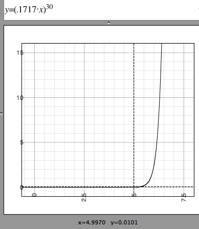
This shows the equation I came up with, as I tried to create a graph that mimics the response of a 5V zener diode.

The scaling coefficient, and the exponent, were both adjusted so that the dotted lines have 5V crossing 10 mA (in agreement with post #1).

4445035300_1403009538.png


The exponent is so high that we can only call it approximate. It might be 20 for one diode, 40 for another.

My equation does not consider ohmic resistance in the diode.

My equation is only a simple convenient model. It does not derive from the Shockley diode equation.
 

Status
Not open for further replies.

Part and Inventory Search

Welcome to EDABoard.com

Sponsor

Back
Top