Continue to Site

Welcome to EDAboard.com

Welcome to our site! EDAboard.com is an international Electronics Discussion Forum focused on EDA software, circuits, schematics, books, theory, papers, asic, pld, 8051, DSP, Network, RF, Analog Design, PCB, Service Manuals... and a whole lot more! To participate you need to register. Registration is free. Click here to register now.

Calculating overall VSWR of a matched circuit?

Status
Not open for further replies.

hakim-djz

Junior Member level 2
Joined
Aug 13, 2014
Messages
21
Helped
0
Reputation
0
Reaction score
0
Trophy points
1
Visit site
Activity points
190
Hi all,

I am trying to calculate the overall VSWR of the attached circuit. In ADS I get around 1.078, but how do you do it by hand?

I've tried converting each part into ABCD params and multiplying then converting them back to S or Z and taking S11 or Z11 and working out the reflection coeff, then the VSWR. But can't figure it out.

If anyone can pass a reference material or explain a method, that would be great!

Thanks

data_dsiplay.pngmatched_at_1GHz.jpg
 

Assuming a lossless line, it is easy. input impedance at the front of TL3 is:
TRL2.jpg

So you input your complex load, transmission line impedance and length, and you have the impedance at TL3 input.
You then invert it to get the admittance Ytl3 = 1 / Ztl3

You now do the same with TL4, where the load is a short circuit, i.e. stub load is 0 + j0 ohms impedance. You compute the impedance at the end of the stub where it connects. then again you invert it to find its admittance, Ystub.

You then simply add Ystub + Ytl3 = Yin. This is the input admittance to the entire circuit. Invert it if you want the impedance.

If they are lossy lines, there are similar formulas available, in hyperbolic tangent form, to do the same thing.
 
Last edited:
Hi biff and thanks for your reply.

I've attempted that and my Zin is 5.326+10.135i, which makes sense as the reactance will cancel out due to the matching. However the result that I get in ADS, 1.071 as shown above, is different to what I'm getting with this value which is VSWR of 9.77.

I've attached a snippet of my calculations if you think I'm missing anything.

mathcad_VSWR.JPG
 

Ok solved it!

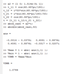
Right, I've attached my matlab code and an attachment of ABCD params formula. The problem I did the first time round was treating the TL4 as a series Z, which is wrong.

So using the formulas. I used the Yshunt ABCD for the s/c stub. The Y value is worked about by tan(β*l)/Zo, where β*l can be found using the stub length 0.018*360 or 0.018*2pi. Dividing to de-normalize an admittance (multiply for impedance). Zo for the stub is different from the system in this circuit. So Ystub = j1.514e-3 mho.

The Tline ABCD formula is used for the tline and after multiplying together and converting to S, then |Γ|= |S11|. Then with Γ the VSWR can be worked out.

Hope this helps others out there.

Thanks Biff for your contribution

Formulas and Code:

20150113_213946.jpgvswr.PNG
 

Status
Not open for further replies.

Part and Inventory Search

Welcome to EDABoard.com

Sponsor

Back
Top