Continue to Site

Welcome to EDAboard.com

Welcome to our site! EDAboard.com is an international Electronics Discussion Forum focused on EDA software, circuits, schematics, books, theory, papers, asic, pld, 8051, DSP, Network, RF, Analog Design, PCB, Service Manuals... and a whole lot more! To participate you need to register. Registration is free. Click here to register now.

Cadence corner simulation

Status
Not open for further replies.

CherryQ

Junior Member level 1
Joined
Feb 1, 2008
Messages
15
Helped
0
Reputation
0
Reaction score
0
Trophy points
1,281
Activity points
1,398
corner simulation

Hi All,

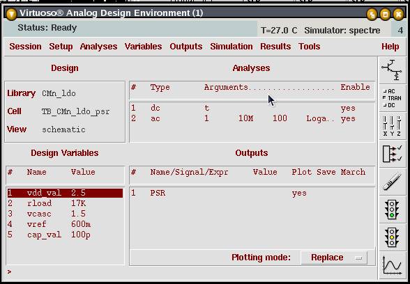
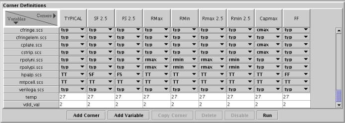
I tried to setup corner simulation in Virtuoso Analog Design Environment/Tools/Corners. By adding variable, I set VDD to be varied according to different corners. By adding corners, I set the required corners, such as typical, ff and ss. However, after i run simulation and plot the VDD from the schematic, it's the same in all corners. May I know anything missing in my setup? Thanks.
 

cadence corners

make shore that the model file is added and it has sections for tt,ff,ss,sf,fs
 

corner simulation cadence

Yes, I did add the modle file and all the sections. I can observe the variation of transistors. But I don't think VDD is included in the model file.
 

cadence corner simulation

Did you use a global VDD ? (with the symbol of analoglib)

Usualy I use pins for my vdd and I put a vdc source in the schematic, so I can vary the voltage value, even in corners.
 

corner analysis cadence

I didn't use global VDD. I did the same way as you. Do you mean to change the value of Vdc source for each corner, or the simulation will auto-change it according to each corner? Thanks.
 

cadence corner

At first I put vdd_val as a variable in the "Analog design environment" it's the value of my power supply source voltage


After that you have to add a new "variable" in the "Analog corners Analysis" tools


Normally you may now vary the value of your power supply simply by changing the value in the box.

Be carefull, as there is a lot of way to do the corners simulations, mainly depending of the design kit you use. I hope this way work equally for you.

In other hand, if this tools dosen't work properly, you may still write an "Ocean" script for yours simulations.
 
corner simulations

You can go to the following link to get a free sample circuit:

**broken link removed**

In this sample circuit, there is a detail step-by-step set up of the Vdd for different corners.
 
corner simulation

if you to test the vdd corners so badly why don't you change it by your hand for example if the supply
spec 1.6-2.2 but vdd=2.2 and then choose the section you want from the model files ff,tt,ss and run the simulation(this depend on the kit you working on try to find it is manual)
 

Status
Not open for further replies.

Similar threads

Part and Inventory Search

Welcome to EDABoard.com

Sponsor

Back
Top