Continue to Site

Welcome to EDAboard.com

Welcome to our site! EDAboard.com is an international Electronics Discussion Forum focused on EDA software, circuits, schematics, books, theory, papers, asic, pld, 8051, DSP, Network, RF, Analog Design, PCB, Service Manuals... and a whole lot more! To participate you need to register. Registration is free. Click here to register now.

Button library in mikroc working

Status
Not open for further replies.

varunme

Advanced Member level 3
Joined
Aug 10, 2011
Messages
741
Helped
17
Reputation
36
Reaction score
17
Trophy points
1,318
Activity points
5,764
How the button library in mikroc works ?

Code:
bit oldstate;                       // Old state flag

void main() {

  ADCON1 |= 0x0F;                   // Configure AN pins as digital
  CMCON  |= 7;                      // Disable comparators

  TRISB0_bit = 1;                   // Set pin as input

  TRISC = 0x00;                     // Configure PORTC as output
  PORTC = 0xAA;                     // Initial PORTC value
  oldstate = 0;

  do {
    if (Button(&PORTB, 0, 1, 1)) {  // Detect logical one
      oldstate = 1;                 // Update flag
    }
    if (oldstate && Button(&PORTB, 0, 1, 0)) { // Detect one-to-zero transition
      PORTC = ~PORTC;               // Invert PORTC
      oldstate = 0;                 // Update flag
    }
  } while(1);                       // Endless loop
}
 

simple,

this library is special for push buttons which are used as follows:

when you press the button you want to execute the needed task one time and to re-execute the task again you should release the button and press it again

but the problem is the infinite loop in the main program is very much faster than the human hand so when you press the button one time the microcontroller normally will execute the task with its speed hundreds of times.

so this library ensures this don't happen, how ?

the initial state is putton released i.e. 0,--this value is stored in a temp variable to compare with, the MCU checks the button continously, when it detects a button press it stores the state of the button in the temp variable (put 1 in the variable) and executes the task needed, then it compares the state of the button with the state of the variable if they are equal that means that the task is completed but the user is still pressing the button.

when the user releases the button, the MCU puts this change in the variable so the variable is 0 again indicating that the MCU is waiting for another press to repeat the prcedure.
 
  • Like
Reactions: varunme

    varunme

    Points: 2
    Helpful Answer Positive Rating
how can i modify it for multiple buttons ?
 

you can copy the same code and past it in the same program under the first one

make sure to change the port pin and the name of the temp variable (i.e. flag2 etc...)
 
  • Like
Reactions: varunme

    varunme

    Points: 2
    Helpful Answer Positive Rating
you can copy the same code and past it in the same program under the first one
make sure to change the port pin and the name of the temp variable (i.e. flag2 etc...)

like
Code:
 oldstate = 0;
 oldstate1 = 0;
oldstate2 = 0;


do {
    if (Button(&PORTB, 0, 1, 1)) {  // Detect logical one
      oldstate = 1;                 // Update flag
    }
    if (oldstate && Button(&PORTB, 0, 1, 0)) { // Detect one-to-zero transition
      PORTC = ~PORTC;               // Invert PORTC
      oldstate = 0;                 // Update flag    
    }


   if (Button(&PORTB, 0, 1, 1)) {  // Detect logical one
      oldstate1 = 1;                 // Update flag
    }
    if (oldstate1 && Button(&PORTB, 0, 1, 0)) { // Detect one-to-zero transition
      PORTC = ~PORTC;               // Invert PORTC
      oldstate1 = 0;                 // Update flag


      if (Button(&PORTB, 0, 1, 1)) {  // Detect logical one
      oldstate2 = 1;                 // Update flag
    }
    if (oldstate2 && Button(&PORTB, 0, 1, 0)) { // Detect one-to-zero transition
      PORTC = ~PORTC;               // Invert PORTC
      oldstate2 = 0;                 // Update flag
  } while(1);

?
 

you seem to not understand the inputs of (Buttons)

Buttons( &selected port, selected pin from port, time ,active state)

where time is the debounce time which the time the MCU waits as a delay to remove parasitic effects like noise

and active state is the number in which if the MCU finds the pin the same as this number the function will return 1 else it will return zero

so if you want to check port b pin 1 for a change from 0 to 1 you write

Button(&PORTB, 1, 1, 1)


so your program must be

oldstate = 0;
oldstate1 = 0;
oldstate2 = 0;


do {
if (Button(&PORTB, 0, 1, 1)) { // Detect logical one
oldstate = 1; // Update flag
}
if (oldstate && Button(&PORTB, 0, 1, 0)) { // Detect one-to-zero transition
PORTC = ~PORTC; // Invert PORTC or Action 1
oldstate = 0; // Update flag
}


if (Button(&PORTB, 1, 1, 1)) { // Detect logical one
oldstate1 = 1; // Update flag
}
if (oldstate1 && Button(&PORTB, 1, 1, 0)) { // Detect one-to-zero transition
PORTC = ~PORTC; // Invert PORTC or Action 2
oldstate1 = 0; // Update flag


if (Button(&PORTB, 2, 1, 1)) { // Detect logical one
oldstate2 = 1; // Update flag
}
if (oldstate2 && Button(&PORTB, 2, 1, 0)) { // Detect one-to-zero transition
PORTC = ~PORTC; // Invert PORTC or Action3
oldstate2 = 0; // Update flag
} while(1);
 
Last edited:
  • Like
Reactions: varunme

    varunme

    Points: 2
    Helpful Answer Positive Rating
ohh thanks
 

Hi guys :)
It's my first contribution :)
Anyway, i'm beginner in Pic programming and have a simple problem hope to find someone can help

The button don't work correct, it just turn on the LED but don't turn them off
Code:
bit oldstate;			  // Old state flag

void main() {

  ANSEL  = 0;			  // Configure AN pins as digital
  CMCON  = 7;			  // Turn off the comparators
  TRISIO = 0;			  // configure pins of GPIO as output
  TRISIO3_bit = 1;
  GPIO = 0xFF;


 while(1){

     if(Button(&GPIO,3,1,1)){
       oldstate=1;
     }

     if(oldstate && Button(&GPIO,3,1,0)){

       GPIO = ~ GPIO;
       oldstate = 0;
     }

            
 }

}


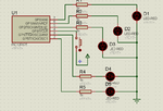
And here is the circuit
Ussntitled.png
 

Zip and post your project files and proteus file. I think if you connect a 10 K pull down resistor from pin GP3 to GND it will work.
I tried the pull down but it doesn't work :)
Thank you for your reply ... Here is the file
**broken link removed**
 

You have used

Code C - [expand]
1
GPIO = ~GPIO

It is wrong because GPIO consists of GP1 to GP5. GP3 is Input pin which also gets affected by the statement

Code C - [expand]
1
GPIO = ~GPIO

So, you have to use something like

Code C - [expand]
1
GPIO.F1 = ~GPIO.F1

You have to invert individual bit except GP3.

Also you have set MCLR enabled in GP3 pin. Set that to disabled and compile the code. You have not selected I/O function on pins 4 and 5. You have to select it.
 

Attachments

  • Project.rar
    35.9 KB · Views: 124
  • button.rar
    607.7 KB · Views: 134
Last edited:

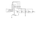
I think the problem is button. It is does not interface correctly.
Try this one.
button.gif
 

yea! this line "GPIO = 0xFF;" chanange to "GPIO=0x00;"
 

@Denshil .. Thanks a lot it does work :)
@jayanth.devarayanadurga ... How can i "set MCLR enabled in GP3 pin" & What do you mean "You have not selected I/O function on pins 4 and 5" :)
Thanks in advance
 

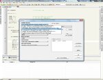
Go to Project>Edit Project... and in the dialog box you have to select INTOSC and IO function on GP4 and GP5 (I think it has a option something like that)
Also there is option for GP3 MCLR Enabled/Disabled.
 

Attachments

  • mikroC.jpg
    mikroC.jpg
    282.3 KB · Views: 201

Status
Not open for further replies.

Part and Inventory Search

Welcome to EDABoard.com

Sponsor

Back
Top