Continue to Site
Follow along with the video below to see how to install our site as a web app on your home screen.
Note: This feature may not be available in some browsers.
If the burnt thing was the power supply input to the board (probably not), accidental reverse polarity can be a problem that burns boards. Using the 'wrong' adapter (e.g., a wall plug-in AC in and DC 5V or 12V out type) which has a barrel jack male that has + and - inverted to the board barrel jack female + and - connections (inner and outer ring) is a good way of burning boards or seeing smoke first and disconnecting before major damage is done if lucky. Always check the picture on the plug/adapter and on the device before using to ensure they match polarity orientation, or test adapter barrel jack with DMM voltmeter.
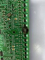
If the design is any indication, the concerned item is most likely a transistor. There are very similar ones (appearances can be deceptive) in the neighborhood but they are intact.
Please find the other side of pneumatic board.
Sorry I’ve already installed new board in machine and it was taken by user.