Continue to Site

Welcome to EDAboard.com

Welcome to our site! EDAboard.com is an international Electronics Discussion Forum focused on EDA software, circuits, schematics, books, theory, papers, asic, pld, 8051, DSP, Network, RF, Analog Design, PCB, Service Manuals... and a whole lot more! To participate you need to register. Registration is free. Click here to register now.

building lm2596 dc dc using Arduino uno

Status
Not open for further replies.

johnny78

Full Member level 4
Joined
Jun 28, 2017
Messages
206
Helped
0
Reputation
0
Reaction score
4
Trophy points
18
Activity points
1,701
hi Guys
i need to use an MCU as a voltage regulator
read about pwm & checked for some projects on the net
would you check this please ?

Schematic_NO_feedback.png

first i think the mosfet is connected wrong way (or im wrong) ?
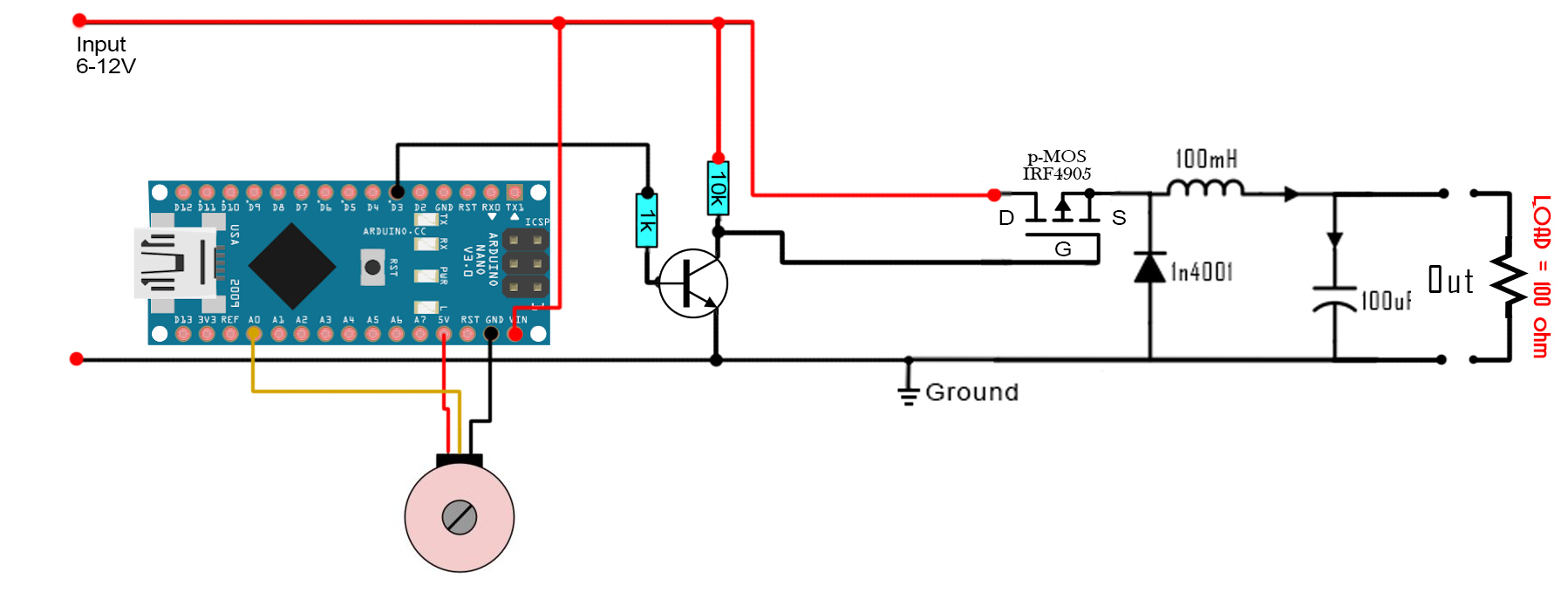
after correcting the connection(S is the input & D is the output) & upladed the simple pwm code to my UNO
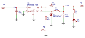
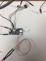
& build the citcuit on 3A dc dc buck conveter which i have removed the lm2596 & connected the IRF4509 on it
but it didt work as a regulator


& tried to drive the mosfet with arduino uno with this code
Code:
/*
 * This is an example code for a BUCK converter circuit made with arduino
 * I've used arduino NANO. We have to set the timer of the PWM on pin D3
 * No feedback is connected here
 * Subscribe: http://www.youtube.com/c/electronoobs
 * webpage: http://www.electronoobs.com/eng_circuitos_tut10.php
 */

int potentiometer = A0; //From the main potentiometer
int PWM = 3;         


void setup() {
  pinMode(potentiometer, INPUT);
  pinMode(PWM, OUTPUT); 
  TCCR2B = TCCR2B & B11111000 | B00000001;    // pin 3 and 11 PWM frequency of 31372.55 Hz
}

void loop() { 
 
  float voltage = analogRead(potentiometer);
  int VALUE = map(voltage,0,1024,0,254);
  analogWrite(PWM,VALUE); 

}
 

Hi,

There are lot of discussions here and even more in the internet about driving a high side MOSFET.
Thus I recommend to do a search on this topic.

100mH is a rather huge inductance. Are you sure this is the correct value?
1N4001 is a rather slow diode .. and it´s not rated for 3A. Not suitable for your circuit.

There is no voltage feedback in your circuit. .. but the LM2596 has.

You won´t get regulation speed, resolution, PWM frequency like the LM2596.
How "close" do you need to work it like the LM2596?

Klaus
hi Klaus
im just testing on the 3A converter board with the installed components just removed the lm2596 & i couldnt upload the circuit of it
i need to test the idea of driving high side mosfet & using it as regulator

i have found another page which includes the same circuit but the mosfet connection is corrected
buck_converter_schematic2.png

thanks for your reply
Johnny
 
Last edited:

hi Guys
here is the first code i used for test which isnt working
Code:
/*
 * This is an example code for a BUCK converter circuit made with arduino
 * I've used arduino NANO. We have to set the timer of the PWM on pin D3
 * No feedback is connected here
 * Subscribe: http://www.youtube.com/c/electronoobs
 * webpage: http://www.electronoobs.com/eng_circuitos_tut10.php
 */

int potentiometer = A0; //From the main potentiometer
int PWM = 3;         


void setup() {
  pinMode(potentiometer, INPUT);
  pinMode(PWM, OUTPUT); 
  TCCR2B = TCCR2B & B11111000 | B00000001;    // pin 3 and 11 PWM frequency of 31372.55 Hz
}

void loop() { 
 
  float voltage = analogRead(potentiometer);
  int VALUE = map(voltage,0,1024,0,254);
  analogWrite(PWM,VALUE); 

}
i was searching & i have found another example with some explanation
But it didnt work too
Code:
#include <Arduino.h>

//Analog input pin for the potentiometer
int potentiometer_pin = A0;

// PWM output pin
int pwm_pin = 3;         


void setup() {
  // Adjusts the pin to input mode
  pinMode(potentiometer_pin, INPUT);
  // Adjusts the pin to output mode
  pinMode(pwm_pin, OUTPUT);

  // Adjusts the PWM frequency to 980.39 Hz.
  // By default arduino PWM frequency is 490.20 Hz,
  // but this value is not high enough to have a stable DC output voltage in low duty cycles.
  TCCR2B = TCCR2B & B11111000 | B00000011;
}

void loop() { 

  // Reads the voltage of the potentiometer to a value between 0 to 1023
  // The resolution of ADC on Arduino is 10 bits.
  int duty_cycle = analogRead(potentiometer_pin);

  // Maps the value from [0 1023] to [0 255] for the PWM function of Arduino
  int duty_cycle_mapped = map(duty_cycle, 0, 1024, 0, 254);

  // Sets the PWM signal duty cyle value, 0->0%, 254->100%
  analogWrite(pwm_pin, duty_cycle_mapped);
}
any useful guide you suggest to start with will be great

thanks in advance
Johnny
 

As pointed out earlier w/o feedback from output back to Arduino,
using Arduino A/D to read voltage, you do not have a regulator ?
So you do not care that as load changes the output V changes ?

Just curious.


Regards, Dana.
 

As pointed out earlier w/o feedback from output back to Arduino,
using Arduino A/D to read voltage, you do not have a regulator ?
So you do not care that as load changes the output V changes ?

Just curious.


Regards, Dana.
sure im intersted to send feedback to the MCU but for now i want to change the volt using PWM
but i have tested another method & didnt work also
a useful example will be great

thanks, Johnny
 

One possibility -

1655640887883.png


The dual curves show 95% and 5 % duty cycle out of pwm. Basically R4 C1, as LPF, convert
duty cycle to a voltage and the NPN Darlington buffers the filter from the load. I used a 1
Khz PWM as model. You have to play with filter values and transistor choice to optimize
for your goals. The darlington drops headroom by two Vbes from the 12V.

An alternative would to be use a power opamp as buffer.

Note there is a large latency out of design due to filter delay, that you can tradeoff
ripple for delay at the load by trying different LPF values.


Regards, Dana.
 
Last edited:

i have tested another method & didnt work also
a useful example will be great
* "it didn`t work" ... means exactly what?
What do you expect? and what do you see instead?

Example:
There are more than enough already availale in the internet. But we don´t know what exactly you are looking for.

LTspice is free. You may use it. Play around.

Klaus
 

Note in your diagram your MOSFET symbol seems to have Source and Drain
connections reversed. Eg. the symbol itself. Your labels on diagram correct
however.

1655644557619.png


1655644519379.png


With respect to the latency problem in post #7 you could play with a non linear
filter in lieu of the RC LPF. For example split filter into two sections, one initial LPF
with low RC time constant, followed by a second section with high RC time constant,
and strap diodes across the R in that section. That way when large steps occur in PWM
duty cycle the diodes conduct and rapidly charge the high valued C in that section,
which shortens latency. Once that C charges the diodes turn off appling the full RC
time constant to the circuit. Standard technique used in PLLs to reduce acquisition time.

Lastly of course an I2C DAC with output buffer would easily produce accurate values
where no fdbk to the Arduino would be needed and latency very short. Just a thought.
Maybe even find one with 100 mA type output capability.......Or sue a power opamp
to handle buffer/current.


Regards, Dana.
 
Last edited:

Other points to note:
1. 1N5819 is the type of diode to use (1N4001 is unsuitable) not the transistor type.
2. to see a change in output voltage you must attach the load, without it the 100uF capacitor will retain the highest voltage placed across it and it will not fall down as the potentiometer is turned.
3. as already pointed out, 100mH is too large to be useful at those frequencies.

If you want to regulate the output voltage, connect a potential divider across the output to scale the voltage to within the ADC range and feed it to a second ADC input. Then, instead of converting the potentiometer voltage directly to PWM ratio, use the difference between it and the divider to decide whether the ratio needs increasing or decreasing. If you want to be clever, check if the output voltage is much lower than it is set to, or is zero to detect whether you have an overload condition or shorted output.

Brian.
 
Note in your diagram your MOSFET symbol seems to have Source and Drain
connections reversed. Eg. the symbol itself. Your labels on diagram correct
however.

View attachment 176972

View attachment 176971

With respect to the latency problem in post #7 you could play with a non linear
filter in lieu of the RC LPF. For example split filter into two sections, one initial LPF
with low RC time constant, followed by a second section with high RC time constant,
and strap diodes across the R in that section. That way when large steps occur in PWM
duty cycle the diodes conduct and rapidly charge the high valued C in that section,
which shortens latency. Once that C charges the diodes turn off appling the full RC
time constant to the circuit. Standard technique used in PLLs to reduce acquisition time.

Lastly of course an I2C DAC with output buffer would easily produce accurate values
where no fdbk to the Arduino would be needed and latency very short. Just a thought.
Maybe even find one with 100 mA type output capability.......Or sue a power opamp
to handle buffer/current.


Regards, Dana.
hi Dana
at start of the thread i have mentioned that the mosfet is connected incorrectly & in the 3rd reply i have attached another circuit with the mosfet connected correctly
 
Other points to note:
1. 1N5819 is the type of diode to use (1N4001 is unsuitable) not the transistor type.
2. to see a change in output voltage you must attach the load, without it the 100uF capacitor will retain the highest voltage placed across it and it will not fall down as the potentiometer is turned.
3. as already pointed out, 100mH is too large to be useful at those frequencies.

If you want to regulate the output voltage, connect a potential divider across the output to scale the voltage to within the ADC range and feed it to a second ADC input. Then, instead of converting the potentiometer voltage directly to PWM ratio, use the difference between it and the divider to decide whether the ratio needs increasing or decreasing. If you want to be clever, check if the output voltage is much lower than it is set to, or is zero to detect whether you have an overload condition or shorted output.

Brian.
here is the circuit of lm2596 module which can regulate the output without connecting a load
its own load is the output led indicator

i have tested the method using this module & have installed IRF4905 with bc337 for driving its gate

what's wrong with my setup for testing ?
 

Attachments

  • 703272845.png
    703272845.png
    18.6 KB · Views: 155
  • 289018660_1747211402337852_7527886859602544015_n.jpg
    289018660_1747211402337852_7527886859602544015_n.jpg
    56.8 KB · Views: 134

which can regulate the output without connecting a load
LED as well as R1/R2 are connected to the output. -->they are "load"

what's wrong with my setup for testing ?
We had a lot of questions -- still unanswered.
Hard to help if yo don´t give these informations.

We don´t know how you tested it, what you expect and what you see instead.

Klaus
 

LED as well as R1/R2 are connected to the output. -->they are "load"


We had a lot of questions -- still unanswered.
Hard to help if yo don´t give these informations.

We don´t know how you tested it, what you expect and what you see instead.

Klaus
thanks Klaus

im expecting to regulate the output when i change the pwm by the potentiometer
what i see is just read the full Voltage at output
it works as switch when i apply any pwm signal to the BC337 base

regards Johnny
 

Hi,

* connect a useful load (as already meantioned you can´t expect regulated output voltage without suitabel load)
* use a suitable MOSFET gate driver (for fast switch OFF)
* do exact voltage measurement of INPUT_VOLTAGE and OUTPUT_VOLTAGE (to see that the voltage varies with duty cycle)
* use feedback

pedantic:
Regulate --> needs feedback. Since you don´t have feedback you can´t regulate.
What you do is "control"... by just using PWM without feedback.


Klaus
 

I don´t know your requirements.
As already mentioned: do a search.

"MOSFET high side driver circuit" gives me more than 3 million hits.

Read through some tutorials and application notes. They really help a lot to understand how it works and then you have the knowledge to decide which feature/function/quality you want for your application and what is not that important for you. I´ve gone through all this, too.

I´m a designer for very "careful" designs. Often the result is quite advanced, other designers may say it is "over complicated". Each designer has it´s own way to do things.

So If I recommend you my preferred solution it´s likely to be too complicated, expensive, maybe with parts that are not avaliable in every region. I tend to go for fast switching edges ... while this reduces switching loss, one needs to do careful PCB layout not to get ringing, malfunction, high noise emitting...

Klaus
 

hi Klaus

you already have mentioned that the LEd is Load or its not enough ?

is controlling pwm this way is enough to control the output ?

Code:
#include <Arduino.h>

//Analog input pin for the potentiometer
int potentiometer_pin = A0;

// PWM output pin
int pwm_pin = 3;         


void setup() {
  // Adjusts the pin to input mode
  pinMode(potentiometer_pin, INPUT);
  // Adjusts the pin to output mode
  pinMode(pwm_pin, OUTPUT);

  // Adjusts the PWM frequency to 980.39 Hz.
  // By default arduino PWM frequency is 490.20 Hz,
  // but this value is not high enough to have a stable DC output voltage in low duty cycles.
  TCCR2B = TCCR2B & B11111000 | B00000011;
}

void loop() {

  // Reads the voltage of the potentiometer to a value between 0 to 1023
  // The resolution of ADC on Arduino is 10 bits.
  int duty_cycle = analogRead(potentiometer_pin);

  // Maps the value from [0 1023] to [0 255] for the PWM function of Arduino
  int duty_cycle_mapped = map(duty_cycle, 0, 1024, 0, 254);

  // Sets the PWM signal duty cyle value, 0->0%, 254->100%
  analogWrite(pwm_pin, duty_cycle_mapped);
}
Code:
 
Last edited:

Hi,

your schematics are inconsistent. Values change form one to the next.

There are free simulation tools. I recommend you to use them. Especially for one with not deep experience they are very helpful to play around with different part values .. to see what happens.

Some basic (mind) calculation:
Your output capacitor is 220uF. A LED current maybe is 10uA. Your switching frequency is about 30kHz (30us)
the basic capacitor formula is: C = I * t / V
Now you have: C, I, t thus you can calculate V
V = I * t / C = 0.01A * 30us / 220uF = 0.3uAs / 220uF = about 0.0015V or 1.5mV
(hopefully my mind calculation is correct. No guarantee for this)
What does this 1.5mV mean:

The capacitor gets charged (30kHz) and discharged (by the LED). In best case - at almost zero duty cycle - the LED is able to drop the capacitor voltage by 1.5mV each cycle.
So if the average current through the coil is just a bit higher than the 10mA then the capacitor voltage will rise to the maximum.
Now how high is the inductor current? There is AC current (often measured in RMS) this can be calculated with frequency and inductance. It is not of interest here. Of interest is the average current. or DC current. And as you know inductors are low impedance for DC. Thus you need onle a very tiny duty cycle to get 15mA of average inductor current.

Sadly you miss to answer about your real coil inductance. As mentioned 100mH seems not to be a realistic value.
I don´t do calculations with this value.

With 30kHz and 8 bit PWM resolution you get the smallest ON_time of 30us/256 which is about 0.12us
Let´s calculate with 100uH (instead of 100mH).
L = V * t / I --> I = V * t / L = 10V * 0.12us / 100uH = 12mA
The average current on a DCM 10V_in 5V_out, 1/256 duty cycle is 12mA *3 / (2 * 256) = 70uA.
This is far below 12mA. Seems to be good.

But if you run a simulation you will see that your MOSFET turns on fast, but very slowly switches OFF. Thus you never get a true ON time close to 0.12us.

Klaus
thanks for the useful informations
its not my schematics im Just trying to test controlling by PWM
I've said before & atteached picture of my real hardware working on
its an lm2596 buck dc dc converter which i just removed the IC & work on the ready made board with its own parts installed
220uf at the output & the iductor valuse is 470 uH

thanks
Johnny
 

Status
Not open for further replies.

Similar threads

Part and Inventory Search

Welcome to EDABoard.com

Sponsor

Back
Top