Continue to Site

Welcome to EDAboard.com

Welcome to our site! EDAboard.com is an international Electronics Discussion Forum focused on EDA software, circuits, schematics, books, theory, papers, asic, pld, 8051, DSP, Network, RF, Analog Design, PCB, Service Manuals... and a whole lot more! To participate you need to register. Registration is free. Click here to register now.

[SOLVED] Building LC Meter Circuit

Status
Not open for further replies.

ozcanay

Newbie level 6
Joined
Jul 22, 2016
Messages
13
Helped
0
Reputation
0
Reaction score
0
Trophy points
1
Activity points
139
Understanding LC Meter

Hi,

I am currently working about creating a LC Meter. I have come across with this project on the internet :

https://electronics-diy.com/lc_meter.php

And the same project a little bit twisted and with some explanations included :

**broken link removed**

I am just interested about the components around LM311. I guess I understood the purpose of those 100k resistors around the (+) pin of LM311 Opamp. Sort of changing voltage between 2VD/3 and VD/3 as explained here :

https://www.romanblack.com/onesec/CapMeter.htm

That relatively large 10uF capacitor is placed there for decoupling purposes I guess. I am aware of the fact that comparator outputs 1 or 0 (0v or 5V in this case) depending on the magnitude of the values on (+) and (-) pins. I figured out well how the calibration is done, and how capacitor and inductance values measured with f1 and f2 values known. But the things is I was not able to understand how f1 and f2 values are measured. I actually know that they are measured by looking at the comparator output period. However I don't know how comparator output is shaped up like that. Also I don't know the purpose of 10uF and 47k at the (-) pin of LM311

Thanks for all the help in advance.
 

Re: Understanding LC Meter

The 10uF and 47K are to provide negative feedback to stabilize the output pin of the LM311. Without them the gain would be so high that even the tiniest discrepancy in input voltage would drive the output either high or low. The resistor provides the voltage feedback and the capacitor ensures the AC gain is very high so the circuit can oscillate freely.

f1 and f2 are measured using the internal timer inside the PIC. It can measure quite accurately because the timer source is derived from the crystal.

Brian.
 
Re: Understanding LC Meter

some other lc meters for your thinkings...
**broken link removed**
 

Re: Understanding LC Meter

OK For mearure LCR you need
1. measuring signal source AC
2. measure the Voltage at the DUT
3. measure the Current over the DUT
4. measure shift between Voltage and Current
One of the methods of measurement is called Auto-balancing bridge method
**broken link removed**

Zx=Vx / Ix = Rr * (Vx/Vr)
Problem is how simple and precise make in Low point virtual ground with 0V potential.
Perhaps they try

**broken link removed**

My quick design building blocks.
1.Signal source I
Impedance 100Ohm, Amplitude +- 1.25V , frequency 100,1k,10k and 100kHz. Optional with DC bias.
Signal source is DDS AD9833 with 18MHz clock , on output is 3th order LPF on 100kHz,
U3 is 8bit digital potentiometer 1kOhm for precise trimming output amplitude on +-1.25V
U1A amplify 0.6V from DDS on +-1.25V, U1B make optional voltage DC voltage offset for output . R7 define output impedance on 100 Ohm.
SQR for 100kHz output signal is 81.5dB, for 10kHz 91.5 dB etc.

DDS.png

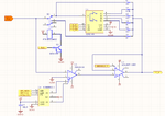
4.Current to voltage converter
Current through the DUT is nulled reverse current passing through resistor. In schematic is used 6 resistor 10,100 Ohm, 1k Ohm, 10k,100k and 1M , resistor is selected with CMOS Switch U3 and 10 ohm with relay K1
Voltage (current) behind DUT is measured with precise amplifier U3 AD8610 + low noise buffer U2 , this on selected R make voltage where
Vr = R*Ir
U4 is used for nulling offset voltage

ItoV.png

2,3 Measure Vr and Vx
Vx and Vr is identical therefore, we will discuss only Vx.
First stage, first tree amplifier is precise instrumentation amplifier wit A= 1x ,2x ,5x ,10x and 20x.
Second two amplifier is 5th order active LPF, which reduce noise on 5MHz over -83dB (assuming use 12bit ADC 10MSPS). Last amplifier shift voltage level from +-1.25V to 0-2.5V for ADC and drive ADC.
C5 blocking DC voltage if DC bias is used. R2 define minim current over C5 some may be omitted

amplifier.png

Then add enough STM32F303 first 2 ADC use for samplig Vx and second two for samplig Vr. Use some digital filter and have simple, precise LCR
What do you think about it?
 
Re: Understanding LC Meter

I have one more question about this project, for the project in the link below :

**broken link removed**

which has source code in the link below :

**broken link removed**

I wonder how the LM311 output frequency is measured in this code. I am not familiar with PIC so I had no clue what the code was all about. I particularly want to know what is happening inside measureLC() function. If I want to implement this circuit with my STM32F429VG, all I have to do is initializing timer when LM311 output becomes 1 and stop the timer when the output goes down to 0. So I will have acquired the period which I can convert to frequency easily. Am I right?
 

Re: Understanding LC Meter

Yes, thats basically correct.

I'm not familiar with STM code so I can't advise on exact instructions but the principle is to set the timer so it counts at a known rate, you probably only have to do that once then leave it running. To time the period, zero the counter at the start of the measurement and capture it at the end. That gives you the number of times the counter incremented during one measurement period. From that you can work out the period (number of counts * counter rate) and the reciprocal is the frequency (1/period).

Brian.
 

Re: Understanding LC Meter

I have one more question about this project, for the project in the link below :

**broken link removed**

which has source code in the link below :

**broken link removed**

I wonder how the LM311 output frequency is measured in this code. I am not familiar with PIC so I had no clue what the code was all about. I particularly want to know what is happening inside measureLC() function. If I want to implement this circuit with my STM32F429VG, all I have to do is initializing timer when LM311 output becomes 1 and stop the timer when the output goes down to 0. So I will have acquired the period which I can convert to frequency easily. Am I right?

yes the program handle the count like that. that way you can go higher than a normal procedural method.
using this technique you can measure frequencies up to 50MHz with a single 10MHz PIC or Atmel
 

Hi,

I am building the circuit given in the link below :

**broken link removed**

It basically generates(supposed to generate) output at the frequency of resonance of the tank circuit. This is done by LM311 IC.

simulasyon.PNG

I built the circuit above just to see if this topology works. But I was not able to get an expected result. This may be because of the fact that PINs 5 and 6 of LM311 are not modelled in pspice. I did time domain analysis simulation.

The result I get for from 0 to 100ms :

100msGrafik.PNG

The result I get for from 0 to 1000 ms :

1000msGrafik.PNG

As it can be seen, there is no square wave output as expected. What could be wrong here? Does it have something to do with the unmodelled pins? Or could it be me building wrong circuit?

Links below explain the working principle of the circuit :

**broken link removed**

**broken link removed**

Thanks in advance.
 
Last edited by a moderator:

Don't know how you managed to make the PSpice simulation not work. It works fine for me.

100 ms analysis time is unreasonably long, may be that it sets in inappropriate time step. 100 µs better fits the high resonance frequency. Or use larger L and C values.
 
Did you use the same C and L values given in my post? Can you share the simulation settings? If it worked on you I guess I did something wrong on settings. I am noob on pspice so I am likely to make a mistake.

Btw which version of pspice have you used for simulation?

Thanks in advance.
 

Hi,

I used 100us as simulation time. At first it didn't work at all, yielding unreasonable triangular waves at the output. Then I checked the checkbox in the simulation settings named "Skip the initial transient bias point calculation(SKIPBP)". Then everyting started to work fine so I guess I had to check that checkbox. Can anyone point me out why that is the case?


11.PNG

That is the time domain simulation for 10us.

Thanks.
 

Skipping initial transient solution is always a good idea for oscillator simulations. The simulator can put an oscillator into perfect equilibrium without any means to stoke up an oscillation. It needs an initial kickstart or non-equilibrium initial bias point to overcome to start.

The unusual point is that we see a small initial oscillation which decays again. This may be due to a "too clever" solver engine which tries to overcome local convergence problems of intentionally stable circuits, probably a feature of newer Pspice versions.
 
Hi again,

I wanted to modify the circuit given above by placing a capacitor parallel to 1nF capacitor.
edadever.PNG

And then I got a weird simulation result (I checked "Skipping initial transient solution" in simulation settings). I wonder why placing a large parallel capacitor disrupts wave this much.

graf.PNG

Thanks in advance.
 

Yeah I am doing that just to try.
 

Hmmm....

That shifts the frequency from 5.558MHz (10pF) to 5.558KHz (10uF) the LC ratio is so wrong the chances of it oscillating, at least as an LC circuit are quite remote.
You might possibly find it produces output as an RC oscillator with R6 and C4 deciding the frequency (C6 would be shorted out at LF by the inductor). That wouldn't let you use it to measure L and C components though.

Brian.
 
According to the link I have used :

**broken link removed**

I am gonna have to place a 10uF(!) capacitor parallel to 1000 pF calibration capacitor for the measuring process if I am to measure the value of 10 uF. When I do the math I see that I will get an frequency of 5558 Hz as you have stated. And when I am measuring the freq. with microcontroller I actually get freq. close to 5550 Hz (actually ~7500, ~8000). So the point is, I am getting a reasonable answer from microcontroller even though the simulation for this configuration is not what I was expecting(sqaure wave). I just have trouble understanding at this point. How is it working if the simulation is wrong. There must be something wrong with the simulation maybe??
 

Surprisingly, the circuit even oscillates with C6 of 10 µF in my PSpice simulation.

I noticed that you have modified the circuit to 3V output supply without adjusting the bias point respectively, resulting in a asymmetric duty cycle,

The post #14 simulation is useless because you didn't change the simulation time according to expectable oscillator period. Similar problem as before, just opposite direction.
 
The result is as expected but for the wrong reasons, I suspect it you short out C6 completely it will still show a similar frequency.

What is happening is the dominant frequency selecting component is now C4. Normally, it's value is very large compared to the LC parts you are measuring and it becomes almost invisible to the signal leaving the L and C to decide the frequency. When you make C6 large as well, the inductor starts to look like a short circuit across it and it plays little part in deciding the frequency. What you are left with is an RC oscillator using the comparators inversion and feedback through R4 to charge and discharge C4.

The LC components will still play some role in setting the frequency but not enough to be able to use it for measurement purposes.

Brian.
 
Status
Not open for further replies.

Similar threads

Part and Inventory Search

Welcome to EDABoard.com

Sponsor

Back
Top