Continue to Site

Welcome to EDAboard.com

Welcome to our site! EDAboard.com is an international Electronics Discussion Forum focused on EDA software, circuits, schematics, books, theory, papers, asic, pld, 8051, DSP, Network, RF, Analog Design, PCB, Service Manuals... and a whole lot more! To participate you need to register. Registration is free. Click here to register now.

Buck is not working in AC stabilizer...

Status
Not open for further replies.

antonio rosario

Newbie level 5
Joined
May 10, 2022
Messages
10
Helped
0
Reputation
0
Reaction score
0
Trophy points
1
Activity points
44
Hi,
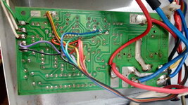
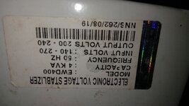
when input voltage is high, output voltage of the stabilizer also high.
I am a beginner in electronics.

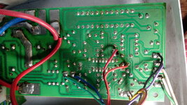
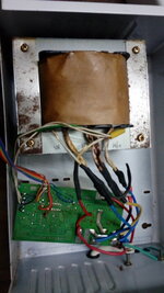
Buck is not working in AC stabilizer. Find no physical damage on the PCB. relay contacts working fine. tried checking diodes and transistor for relay to on off, all are with multimeter.

There is no low high cut preset in this PCB, only one preset is there for LM324n to run properly.

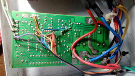
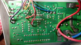
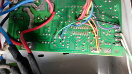
Kindly find the pictures for your reference.

[Edit]Link to external server deleted, please attach pictures directly.

1654435285098.png
1654435495127.png
 
Last edited by a moderator:

pictures uploaded. Thanks moderator.
 

Attachments

  • IMG_20220605_133146.jpg
    IMG_20220605_133146.jpg
    3.7 MB · Views: 85
  • IMG_20220605_133355.jpg
    IMG_20220605_133355.jpg
    2.9 MB · Views: 93
  • IMG_20220605_133417.jpg
    IMG_20220605_133417.jpg
    3.3 MB · Views: 87
  • IMG_20220605_133440.jpg
    IMG_20220605_133440.jpg
    2.9 MB · Views: 91
  • IMG_20220605_133508.jpg
    IMG_20220605_133508.jpg
    2.9 MB · Views: 80
  • IMG_20220605_133532.jpg
    IMG_20220605_133532.jpg
    3.5 MB · Views: 83
  • IMG_20220605_133615.jpg
    IMG_20220605_133615.jpg
    2.4 MB · Views: 85
  • IMG_20220605_145058.jpg
    IMG_20220605_145058.jpg
    2.7 MB · Views: 87

324 is quad op amp whose supply is low voltage DC. Buck converter implies step down DC. The relay coils are labelled for 12V presumably DC.

However the label implies AC-to-AC conversion. The relays are labelled for mains voltage AC.

My (wild) guess is that's a large auto-transformer. The relays can switch the secondary winding in either direction to perform buck or boost action. The range of performance allows leeway for it to add 70v or subtract 70v.

Visually the board appears okay. The 324 can fail with no outward sign. Maybe it can drive the relay coils, or maybe it needs assistance from neighboring transistors? I think the manufacturer put that IC in a stressful role.

Are you certain it's receiving power? The supply can be more than 15V, maybe as high as 35v. If it's not present then can you figure out hook up an external supply? Can you operate the relays by connecting it to 12V? Do the least invasive steps first, because anything you do risks ruining the board.
 
@BradtheRad checked the relay with external 12v DC and connected the relay contacts with multimeter in diode mode, relay contacts are working fine. power supply to relay have BD139 transistor and checked with multimeter. its giving value and not shorted. also same with Diode, no shorted or open.
I have tested this AC stabilizer by connecting a manual boost or buck stabilizer has 8 step increase or decrease knob. while increase or decrease the knob the relay gives click sounds so the IC is in working condition I think so, also LED are glow in right way.

I want to know whether the transformer giving the buck or not. Since its a hot line I'm afraid to do checking with multimeter. how to know whether the transformer is giving +30 and -30V with or without live test by multimeter. on PCB which wires are +30 or -30V. I have read in google that -30V is by turning coil in opposite direction to +30V coil.

Also resistors in row are showing less value for example 2.2K ohm color code shows 1.2K in multimeter, Is that variation OK or need to change the resistors ?
How much difference is acceptable in resistor value ?
 
Last edited:

Resistors almost never go bad to the extent of changing value as you describe. Your reduced ohm readings suggest a parallel component is practically shorted.

Did you check ohm readings of the 324 pins? Use the highest (1M) range rather than the lowest (200 ohm) range. If many pairs yield a similar low reading then its innards are no doubt fused together.

If the 324 were socketed it would be easy to say 'Replace it with new'. However to desolder it is a headache. For now test other simpler things.

A variac would come in handy right now. And an isolation transformer. As a substitute you might jumper an incandescent lamp bulb in series with your unit. 100W is about 200 ohms at 220VAC.

It sounds as though the transformer contains 2 or more windings? (4 thick wires go to it.) (The remaining two small wires most likely convey low voltage to the board.)
One spark arc event can create a shorted winding, then the whole thing stops working. And most likely overheats due to extreme Amperes going through it. Arcing can happen if shutting off high current through of a very high inductance load, or if a lightning strike sends a high voltage surge through the lines.

Eventually you may need to test each winding for inductance (Henry) and resistance values, and all parameters that might give you a hint whether any winding is bad. Also to test step-up or step-down capability.
To do it properly you must disconnect all wires to the transformer, and tag each wire. It's tedious. If you find a winding is broken (open or shorted), then you must remove all turns until you find the problem, fix it, then wind all wires back up. This is such a big job that you should first try every test possible with a meter, or lamp bulb, etc.
 
Status
Not open for further replies.

Part and Inventory Search

Welcome to EDABoard.com

Sponsor

Back
Top