Continue to Site

Welcome to EDAboard.com

Welcome to our site! EDAboard.com is an international Electronics Discussion Forum focused on EDA software, circuits, schematics, books, theory, papers, asic, pld, 8051, DSP, Network, RF, Analog Design, PCB, Service Manuals... and a whole lot more! To participate you need to register. Registration is free. Click here to register now.

buck converter operates in DCM mode

Status
Not open for further replies.

themaccabee

Full Member level 4
Joined
Apr 1, 2007
Messages
201
Helped
6
Reputation
12
Reaction score
6
Trophy points
1,298
Activity points
3,003
Hi,

I want to know one thing about a buck converter in DCM mode ..may b its silly..But my question is..

When the buck converter operates in DCM mode and is in steady state..

1)will the current through the inductor rises as soon as the switch is turned ON?


2)Assume a 10V to 5V/1A buck regulator..It is in steady state with 5R load connected..
Now the load resistor is increased to high value..so current drawn is negligible..
Now as the switch turns ON inductor sees a voltage difference across it and current through it rises..Till the Ton period is over.Now as Toff begins inductor current flows through the diode..So unlike in CCM why the inductor current dies off quickly?.
May be the capacitor is not getting discharged as in the CCM case & the peak inductor current is not same as in the CCM case..
May be whole thing is silly but im quite unclear about the operation in DCM..
can some one help me ?
Thanks
 

Hi,

I want to know one thing about a buck converter in DCM mode ..may b its silly..But my question is..

When the buck converter operates in DCM mode and is in steady state..

1)will the current through the inductor rises as soon as the switch is turned ON?
Yes, the inductor current always starts rising right after the switch turns on.

2)Assume a 10V to 5V/1A buck regulator..It is in steady state with 5R load connected..
Now the load resistor is increased to high value..so current drawn is negligible..
Now as the switch turns ON inductor sees a voltage difference across it and current through it rises..Till the Ton period is over.Now as Toff begins inductor current flows through the diode..So unlike in CCM why the inductor current dies off quickly?.
May be the capacitor is not getting discharged as in the CCM case & the peak inductor current is not same as in the CCM case..
May be whole thing is silly but im quite unclear about the operation in DCM..
can some one help me ?
Thanks
I'm not really clear on what you're asking... if you want to discuss specific circuit operation, you'll have to give more details (and also the role of feedback is important).

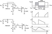
The rate at which inductor current rises and falls within a switching cycle is only dependent on the input and output voltages, and the inductance. During the switch ON time, di/dt=(Vin-Vout)/L, and during the OFF time di/dt=(-Vout)/L (neglecting diode drops and such). But the inductor current will never actually fall below zero. When it falls to zero within a switching cycle, that's called DCM. In DCM, the inductor current will start at I=0 when the FET turns on. So the exact current waveforms at steady state can be derived pretty easily (you just need to know Vin, Vout, L, and either the load resistance or current).

For looking at transient response of the converter over several switching cycles, you need to start looking at small signal models, which is more complicated.
 

When it falls to zero within a switching cycle, that's called DCM
Exactly ..so what causes the inductor current to fall to zero?? say in a specific case of buck converter..


it is generally said as the decrease in load current forces IL to come down..delta IL finally touches the zero line..So how will be the current & its path during that time..
Thank for any help
 

During ON time, you store energy in the inductor's magnetic field. During OFF time, it gets utilized to charge the output cap. In DCM you utilize all this energy.
Another point to consider is that in case of a synchronous buck converter, those have a MOSFET (/BJT/IGBT..) instead of the flyback diode. If you control this low side MOSFET to open for the entire OFF time, it can happen that the inductor current goes negative (turns direction) during OFF time, actually discharging the output cap. Luckily, in this case this energy will not be lost however. At the next ON time, the inductor will deplete this reverse magnetic field energy to charge the INPUT capacitor, by pushing the reverse current through the HIGH side MOSFET.
In case of an asynchronous converter, the flyback diode stops the process at zero current, and the inductor current can't reverse, because of the diode's orientation.

Was this what you were unsure about?

Good luck,
Gabor
 

Status
Not open for further replies.

Similar threads

Part and Inventory Search

Welcome to EDABoard.com

Sponsor

Back
Top