elthanor
Newbie level 2

- Joined
- Mar 26, 2014
- Messages
- 2
- Helped
- 0
- Reputation
- 0
- Reaction score
- 0
- Trophy points
- 1
- Activity points
- 19
Greetings,
I am new to this forum and i would like some assistance in a problem that i face.Using Proteus and reading through the internet i have created a Buck converter in order to understand how it works and after that use it in a project.The problem is that even though i think that i have done everything right the circuit refuses to work properly.
Here is an image:

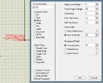
Through the drain of the mos there are 10V and the settings i have for the generator are:

In normal circumstances this should give approximately 5V but instead the output is 10V as well.
Here is the oscilloscope view:

I am deeply frustrated as this is the simplest circuit for a Buck converter and i cant get it right even after spending a whole day searching for the mistake.Any help would be appreciated.
Thanks in advance
I am new to this forum and i would like some assistance in a problem that i face.Using Proteus and reading through the internet i have created a Buck converter in order to understand how it works and after that use it in a project.The problem is that even though i think that i have done everything right the circuit refuses to work properly.
Here is an image:

Through the drain of the mos there are 10V and the settings i have for the generator are:

In normal circumstances this should give approximately 5V but instead the output is 10V as well.
Here is the oscilloscope view:

I am deeply frustrated as this is the simplest circuit for a Buck converter and i cant get it right even after spending a whole day searching for the mistake.Any help would be appreciated.
Thanks in advance
