Continue to Site

Welcome to EDAboard.com

Welcome to our site! EDAboard.com is an international Electronics Discussion Forum focused on EDA software, circuits, schematics, books, theory, papers, asic, pld, 8051, DSP, Network, RF, Analog Design, PCB, Service Manuals... and a whole lot more! To participate you need to register. Registration is free. Click here to register now.

Buck-Boost Converter

Status
Not open for further replies.

Vicneesh

Newbie level 2
Joined
Oct 11, 2016
Messages
2
Helped
0
Reputation
0
Reaction score
0
Trophy points
1
Activity points
15
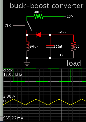
Hello guys. I am a final year student doing a project on buck-boost converter with input of 9V-22V to produce output of 12V. My circuit needs to include power switching device and pwm. Any idea how can I construct my circuit on proteus to simulate? Thank you.
 

You can't get what you want with one converter. There are 2 options; 1. With step up converter convert the input to say 30V and then a step down converter to 12V. 2. Step down converter to 5V and then step up to to 12V.
Option 1 is likely to be more efficient.
 
In case this helps, here's an example drawn in another simulator:

5763673300_1476230936.png


The scope traces portray waveforms as the switch opens & closes.
Notice the output voltage is inverted polarity, a characteristic of buck-boost type.

For supply=9V duty cycle could be 65%.
For supply=22V it might be 38%.
 

Hi,

Look for SEPIC.
LT has ready to buy controllers. Read the datasheets and application notes to understand the working principle.

Klaus
 
Thank you for giving me ideas. Will attempt it and get back if there is any problem. Thank you.
 

Status
Not open for further replies.

Similar threads

Part and Inventory Search

Welcome to EDABoard.com

Sponsor

Back
Top