Continue to Site

Welcome to EDAboard.com

Welcome to our site! EDAboard.com is an international Electronics Discussion Forum focused on EDA software, circuits, schematics, books, theory, papers, asic, pld, 8051, DSP, Network, RF, Analog Design, PCB, Service Manuals... and a whole lot more! To participate you need to register. Registration is free. Click here to register now.

Bridge Rectifier Circuit

Status
Not open for further replies.

Surjeetsinh Chauhan

Newbie level 3
Joined
Jan 1, 2015
Messages
3
Helped
0
Reputation
0
Reaction score
0
Trophy points
1
Activity points
18
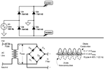
I am Trying to design a simple bridge rectifier on Breadboard by connecting negative of source to ground but when i connect Node 1 to 4 Channel Oscilloscope +ve pin with -ve pin GND , i get Half wave , but when i connect +ve pin to Node 1 and -ve pin to Node 2 i get same half wave at output and Input also becomes half wave how to solve this issue please help ??

rect.jpg
 

Your input sinewave is grounded. Usually the input sinewave comes from a transformer winding without a ground. Then you can ground the negative output (Node 2 on your sketch) and get full wave rectified positive pulses from Node 1.
Look here:
 

Attachments

  • bridge rectifier.png
    bridge rectifier.png
    93.4 KB · Views: 65
Thank you for your reply. i found this circuit on one website using Multisim , where ground is on -ve of input and no ground on other side after rectificationimages.jpg .
 

my issue is with ground pin of Oscilloscope when i connect it to Node 2 my input is getting clipped.
 

Because your input has a ground and your oscilloscope also has a ground then half of the bridge rectifier is shorted.
 

Status
Not open for further replies.

Similar threads

Part and Inventory Search

Welcome to EDABoard.com

Sponsor

Back
Top