Continue to Site

Welcome to EDAboard.com

Welcome to our site! EDAboard.com is an international Electronics Discussion Forum focused on EDA software, circuits, schematics, books, theory, papers, asic, pld, 8051, DSP, Network, RF, Analog Design, PCB, Service Manuals... and a whole lot more! To participate you need to register. Registration is free. Click here to register now.

BPSK Modulator

Status
Not open for further replies.

nyquist23

Newbie
Joined
Jun 2, 2021
Messages
1
Helped
0
Reputation
0
Reaction score
0
Trophy points
1
Activity points
12
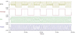
Hello I am currently working on a BPSK modulator (highlighted in blue). The other part of the schematic is just an oscillator circuit which provides 500kHz sine wave signal to the BPSK circuit. My problem is that I am not getting the output that I am expecting. The Vmessage is a square wave with 50kHz frequency.

1622692023162.png


See photo below for the output of the circuit.

1622692302927.png


I don't really know if I put the right components so any ideas would be very much appreciated!! Help a struggling student out :( thanks in advance!
 

Attachments

  • 1622692238368.png
    1622692238368.png
    112.7 KB · Views: 89

An internet article shows the output has a sinewave starting upward in response to a positive-going edge of the incoming message, and starting downward in response to a negative-going edge.

I believe your blue area inverts the phase of the sine-wave? Should the mosfet section have a negative supply similar to the op amps?

Presently it has 0V ground. Does that explain why your troughs don't drop all the way to -5v?
 

This previous thread shows that the topology can basically work https://www.edaboard.com/threads/bpsk-design-with-transistors.398014

I'm not sure what causes the reported behaviour in the present circuit. The waveform doesn't seem to fit the claimed circuit values, it shows a sine of +/- 5V although OP3 has only +/- 5V power supply. That's impossible according to LM318 spec, which would suggest clipping to about +/- 3V. There may be other component value and power supply voltage deviations. A different explanation could be that the component models of your simulator are very inaccurate.

2N4858 has a wide range of Vth, it's not guaranteed to switch off over the full Vsin voltage range with the applied negative gate voltage. You may try to increase OP1 negative supply voltage.

The simulator gives you the opportunity to trace the cause of unexpected circuit behaviour by looking at node voltages and branch currents.
 

Status
Not open for further replies.

Similar threads

Part and Inventory Search

Welcome to EDABoard.com

Sponsor

Back
Top