Continue to Site

Welcome to EDAboard.com

Welcome to our site! EDAboard.com is an international Electronics Discussion Forum focused on EDA software, circuits, schematics, books, theory, papers, asic, pld, 8051, DSP, Network, RF, Analog Design, PCB, Service Manuals... and a whole lot more! To participate you need to register. Registration is free. Click here to register now.

Boost efficiency drop at higher loads HELP please

Status
Not open for further replies.

bowman1710

Full Member level 3
Full Member level 3
Joined
Nov 8, 2014
Messages
183
Helped
6
Reputation
12
Reaction score
6
Trophy points
18
Visit site
Activity points
1,604
Hi guys,

I'm running at boost converter at 18-30V in to 50V 4A output at 333Khz fsw. When I push the load up to about 150W the efficiency takes a nose dive, I assume it because of the losses in the diode, is there anything else that can be effecting it at higher loads?

DesignLM3481.PNG
 

You can try by reducing the value of RS1 and Rsense. When I tried the same design in the WEBENCH with the given spec of 4A. TI have not suggested this part. So when I tried for 3A TI had suggested this part. So make sure regarding the supply current.
 
  • Like
Reactions: Dont

    Dont

    Points: 2
    Helpful Answer Positive Rating
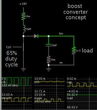
My simulation shows that to obtain 50V at 4A, from an 18V supply...

Requires a waveform with peaks of 60 or 70A, with greater than 90 percent duty cycle. Operating frequency under 10 kHz. I went with an inductor value of 15 uH (although it is uncertain as I look at your schematic).

I believe your duty cycle becomes so long, nearly 100 percent, that output suffers. This is asking a lot from a boost converter. You may get better performance from a flyback topology.
 

Duty cycle should only need to be %65 with Vin=18V, shouldn't be problematic.
Usually efficiency drops slowly at high power due to ohmic conduction losses, since they scale with current squared whereas switching losses should scale with current. The inductor ESR is often a main culprit. The sense resistor could be contributing as well.

Also the filter on your current sense signal is probably much slower than it should be.
 

at 18v = vin, your input current is over 10 Amps, and you could be getting supply lead losses etc too
 

Duty cycle should only need to be %65 with Vin=18V, shouldn't be problematic.

Right, my simulation now has 65% duty cycle, and 13A peak waveform, after I trimmed parasitic resistance to a tiny amount (probably unrealistic).

At 333 kHz, the boost converter is well into CCM (as indicated by scope trace showing inductor current).

The above is theoretical of course.

A real circuit is likely to have greater parasitic resistance, and hence require greater current flows. Diode resistance can contribute to parasitic resistance.

- - - Updated - - -


The Isat current of Inductor should be 1.5 times more than the output current. So please check that in your case and also go to TI website try the same circuit in WEBENCH with spec which is required for you. The manufacturer is not at all suggesting the part (LM3481) which you have for your spec. So better change the part or try to change the values.
 

Status
Not open for further replies.

Similar threads

Part and Inventory Search

Welcome to EDABoard.com

Sponsor

Back
Top