Continue to Site

Welcome to EDAboard.com

Welcome to our site! EDAboard.com is an international Electronics Discussion Forum focused on EDA software, circuits, schematics, books, theory, papers, asic, pld, 8051, DSP, Network, RF, Analog Design, PCB, Service Manuals... and a whole lot more! To participate you need to register. Registration is free. Click here to register now.

boost dc-dc converter voltage

Status
Not open for further replies.

neazoi

Advanced Member level 6
Joined
Jan 5, 2008
Messages
4,123
Helped
13
Reputation
26
Reaction score
15
Trophy points
1,318
Location
Greece
Activity points
36,955
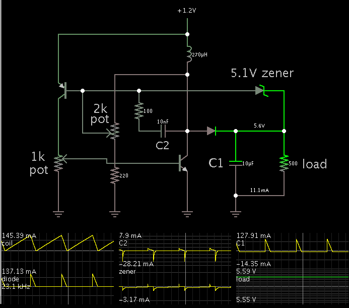
Hello I have made this power inverter https://www.eleccircuit.com/step-up-dc-converter-1-2v-to-5v-5v-for-micro-computer/ for a microcontroller project that uses a atmega644 and two 24c512. I have used a 1n5711 for the schottky and I have not built the negative voltage section.

The micro seems to start at 4.3-4.4v but the maximum loaded output I can get out of the inverter is 4.2v (using a 5.1v zener)
The micro draws less than 1mA I do not know why the drop in the voltage is happening. Anyway the unloaded voltage is 5.1v the same as the zener, but the loaded voltage as I said is 4.2v.

Is there anything I can do to boost this voltage to more than 4.5v instead of 4.2? MAybe more turns on the coil or...?
 

That is a clever way to get boost converter operation from a single cell!

To raise the output you need to increase current through the coil. This is controlled by T1.

Hence you may need to increase its bias current. Try reducing R2 and/or increase R1 (assuming R1 is necessary).

If that does not help then you might need to alter the operation of T2, because current through T1 is controlled by T2. Try reducing the value of R5. This should cause T2 to conduct more, and/or stay on longer. (The same might be accomplished by increasing the value of R4).

R3 and C2 probably are for snubber function, in case spikes are generated by the coil.
 
  • Like
Reactions: neazoi

    neazoi

    Points: 2
    Helpful Answer Positive Rating
That is a clever way to get boost converter operation from a single cell!

To raise the output you need to increase current through the coil. This is controlled by T1.

Hence you may need to increase its bias current. Try reducing R2 and/or increase R1 (assuming R1 is necessary).

If that does not help then you might need to alter the operation of T2, because current through T1 is controlled by T2. Try reducing the value of R5. This should cause T2 to conduct more, and/or stay on longer. (The same might be accomplished by increasing the value of R4).

R3 and C2 probably are for snubber function, in case spikes are generated by the coil.

Thanks! I will try these changes today and let you know if this does not work.
 

That is a clever way to get boost converter operation from a single cell!

To raise the output you need to increase current through the coil. This is controlled by T1.

Hence you may need to increase its bias current. Try reducing R2 and/or increase R1 (assuming R1 is necessary).

If that does not help then you might need to alter the operation of T2, because current through T1 is controlled by T2. Try reducing the value of R5. This should cause T2 to conduct more, and/or stay on longer. (The same might be accomplished by increasing the value of R4).

R3 and C2 probably are for snubber function, in case spikes are generated by the coil.


I have tried all these changes, no success. the most I can ged out of a 1.2v is 4.3v. The strange thing is that even if I try 2.2v input I also get 4.3v output. Something else must be wrong. any guess?
 

I have tried all these changes, no success. the most I can ged out of a 1.2v is 4.3v. The strange thing is that even if I try 2.2v input I also get 4.3v output. Something else must be wrong. any guess?

This suggests your zener diode D4 has a spec of 4.3V rather than 5.1 V.

What causes it to conduct, is when the output rises above its threshold. It conducts to T2's base, causing T2 to conduct less, or else turn off sooner.

Try raising the zener threshold by adding a diode in series. That will add about 0.6V.

If you need to increase it again by an amount less than .6V, add a low-ohm resistor in series.

My cheap Chinese zener is rated at 5v1. I have also tried 6v8 anf 7v2 but if I remember well the voltage was less than 4.3v woth these. I do not know what is happening.
I do not like circuits that are component critical to work, it should work at first time or else it is not good. The only thing I have changed is the bat43 with a 1n5711, which should yeld in similar performance.

I am thinking of switching to another inverter to see how it works. **broken link removed** the first circuit on this page. It is 9v but it should be easy to bring it down to 5v by using another zener. Also no special schotky diode there. I am thinking of using complement 2n2222/2n2907 for the transistors. Any comments?
 

It is evident the converter works, since you are getting a higher output than the battery V.

The diagram shows a coil rating of 200 mA. This may be a ballpark figure for the amount of current to expect. The schematic shows the output is rated 10 mA at 5V. To do this the 1.2 V battery must provide about 100 mA peak each cycle (at 20 kHz, demonstrated in a different boost converter simulation).

Although you are not drawing the entire 10 mA shown in the schematic, are you certain there is sufficient current going through the coil? A multimeter may or may not be able to measure this directly.

Can your battery provide 100 mA, perhaps as much as 200 mA?

Also if the operating frequency is too fast, it does not allow time for sufficient current to build in the coil. (However the hysteresis action is supposed to automatically adjust the frequency to compensate.)

Also a plain silicon diode may not perform quickly enough to conduct sufficient current during a cycle. (Again the hysteresis action should make up for this by reducing the frequency.)

I am thinking of using complement 2n2222/2n2907 for the transistors.

The specs for 2N2222 look as though it should work fine.
 

It is evident the converter works, since you are getting a higher output than the battery V.

The diagram shows a coil rating of 200 mA. This may be a ballpark figure for the amount of current to expect. The schematic shows the output is rated 10 mA at 5V. To do this the 1.2 V battery must provide about 100 mA peak each cycle (at 20 kHz, demonstrated in a different boost converter simulation).

Although you are not drawing the entire 10 mA shown in the schematic, are you certain there is sufficient current going through the coil? A multimeter may or may not be able to measure this directly.

Can your battery provide 100 mA, perhaps as much as 200 mA?

Also if the operating frequency is too fast, it does not allow time for sufficient current to build in the coil. (However the hysteresis action is supposed to automatically adjust the frequency to compensate.)

Also a plain silicon diode may not perform quickly enough to conduct sufficient current during a cycle. (Again the hysteresis action should make up for this by reducing the frequency.)


The specs for 2N2222 look as though it should work fine.

Yes I am using a 700mah AAA battery so I think it should be able to provide this pulsed current. The coil is 10T of thick wire on a ft50-75J core so I think this is ok. I replaced it with a molded choke and the voltage went down to 1v, so I think the coil does a good job. There is something that holds the voltage to 4.3v, since If I feed the input with 1.5, 2 and 2.5v the output voltage stays the same...

I have also tried a joule thief, but It could not provide 5v out of 1.2v, I think it is only useful for LEDs, maybe a voltage doubler after the joule thief could do the job, who knows..
 

I got around to making a simulation. I found that it requires a bit of adjustment to get it to operate.

It helps to put potentiometers instead of R1-R2 and R4-R5. That way you can vary the ratio, looking for a point that will make oscillations begin.


C2 and R3 are necessary to assist in triggering the transistor on and off.

The 220 ohm resistor is a safeguard, to limit current if the pot is dialed to the lower end of travel.

My simulation operates at 20 kHz. Will a real silicon diode perform properly at that speed is the question?
 

I have also tried a joule thief, but It could not provide 5v out of 1.2v, I think it is only useful for LEDs, maybe a voltage doubler after the joule thief could do the job, who knows..

Yes, a joule thief will work too. It is a boost converter.

A diode is needed to prevent the capacitor from losing charge.


The bias resistor should be increased or decreased to create the desired current in the transformer.

I put a switch on the zener diode to show it can be used for voltage regulation. However it wastes a bit of power. I notice how your Eleccircuit.com schematic has an ingenious method... It puts the zener in a position so that it reduces transistor bias when it conducts. That is the efficient way to regulate. However I do not know how to do the same thing with the joule thief.
 
  • Like
Reactions: neazoi

    neazoi

    Points: 2
    Helpful Answer Positive Rating
Status
Not open for further replies.

Similar threads

Part and Inventory Search

Welcome to EDABoard.com

Sponsor

Back
Top