T
treez
Guest

Hello,
Please can you advise on why the Bode plot for an opamp circuit is different depending on whether I use LTspice to get it , or when I calculate it in Excel?
(If I do the Bode plots for a simple, passive RC circuit, then they are the same whether I use Excel or LTspice)
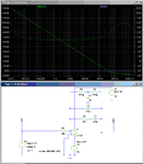
The below shows the opamp schematic in question, and the bode plots, plus LTspice simulation.
For example, at 50.31KHz…
Excel gives a gain of -6.74dB & phase of 163 degrees
LTspice gives a gain of –9.202dB & phase of 155 degrees
Also, as you can see, at low frequencies of around 1Hz, the gain and phase are massively different between Excel and LTspice.
The LTspice bode plot is the red one and the phase is a broken line.
Do you know the reason for the differences?


