righteous
Full Member level 2
Gents,
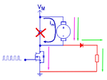
I want to recover as much flyback current as possible from my BLDC, so far I have 200mA going in and I'm only able to recover 1-3 mA's before the voltage after the (hand drawn) diode drops below supply voltage, which is disappointing.
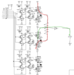
This is the driver stage of my BLDC controller, and I have taken phase 1 as an example

In red the coil gets energized, and the green is where I expect the flyback current to go. Q7 is OFF, but I expect the body diode to conduct.
I have made this online calculation (NB: the switching pulse is V(ds) and not V(g))

And the scope shows that I should be right on the money.

CH1 and CH2 is voltage across a 1 ohm shunt resistor on the high side. The WHITE trace is CH1 minus CH2
And CH3 is the gate switching signal for Q12 the low side FET.
So...where is my flyback current?
I want to recover as much flyback current as possible from my BLDC, so far I have 200mA going in and I'm only able to recover 1-3 mA's before the voltage after the (hand drawn) diode drops below supply voltage, which is disappointing.
This is the driver stage of my BLDC controller, and I have taken phase 1 as an example

In red the coil gets energized, and the green is where I expect the flyback current to go. Q7 is OFF, but I expect the body diode to conduct.
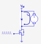
I have made this online calculation (NB: the switching pulse is V(ds) and not V(g))

And the scope shows that I should be right on the money.

CH1 and CH2 is voltage across a 1 ohm shunt resistor on the high side. The WHITE trace is CH1 minus CH2
And CH3 is the gate switching signal for Q12 the low side FET.
So...where is my flyback current?


