Continue to Site

Welcome to EDAboard.com

Welcome to our site! EDAboard.com is an international Electronics Discussion Forum focused on EDA software, circuits, schematics, books, theory, papers, asic, pld, 8051, DSP, Network, RF, Analog Design, PCB, Service Manuals... and a whole lot more! To participate you need to register. Registration is free. Click here to register now.

Bipolar Stepper Motor Driver heat problem

Status
Not open for further replies.

nick703

Advanced Member level 1
Joined
Oct 17, 2011
Messages
422
Helped
21
Reputation
44
Reaction score
22
Trophy points
1,298
Location
surat
Visit site
Activity points
3,987
hello friends i want to create bipolar stepper motor driver.

then i have to choose pin compatible version of ic like A3979 and drv8818 from texas instruments.

now please give me a some hint how to design my pcb to remove heat of ic when current is exceed 2A.

then how to create surface area to remove heat of SSOP-28 pin package. is that required more hole or required more copper plane to remove heat please guide me .

below is the create simple top layer part in ic image.
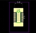
28pin.JPG

please help me how to remove heat then do not required any heat sink . is that possible with top and bottom layer of pcb ?
 

Hi,

read the datasheet.
There is a section called "thermal information"
And there is a example board layout drawing.

Remove heat: You can´t change the disspated power, so you have to transmit the temperature on a large area of your PCB. Copper has a good thermal conductivity. Use thick copper on your PCB.
Use as much copper as you can. Maybe you can´t avoid an extra heatsink.

Hope this helps
Klaus
 

Check the ICs power dissipation & using thermal resistance (Theta ja), calculate the temperature raise. Add the temperature raise with ambient temperature & see it is not exceeding the maximum junction temperature of the IC. According to the thermal margin you get, you can decide whether a heat sink is necessary or not.
 

ok friends now i have a question A3977 and A3979 is pin compatible ok
now below is my circuit diagram of A3977 and i have a same configuration in A3979 . but this time my circuit doesn't work ? is that any additional setting required ? please suggest me .

and my A3977 based driver working completely but A3979 based driver not working why ? every thing diagram pcb and programming same but my this driver not working is that any component required to change ?
and also my A3977 is a PLCC 44 pin version and A3979 is TSSOP 28 pin package version ..a3977.JPG

please kind me suggest best solution . in datasheet every thing same content of A3979 and A3977.
 

i have a further testing my board and i have found some solution when my stepper motor speed increase that time stepper motor miss the pulse and motor vibrate but in A3977 board i have a same speed applied but not any missing the pulse . so how i would to change any component of my stepper board please suggest me bro!!!!!
 

NICK did you fix thermal cooling problem with large ( >4sq in) copper heat sink to substrate of IC? or forced air?

What is purpose of Opto if In, Out share a common ground? Nothing?? convert bipolar pulses to unipolar?

Can you compare Schmitt trigger output signals?
 
hello Sunnyskyguy thanks for reply ,

yes i have large ground plane on TOP and BOTTOM part of my PCB to reduce heat . and now i have also use heat sink for ic cooling .
actually opto - coupler ic is the better solution instead of giving direct pulse . and yes this opto coupler ic also working in my A3977 board .
but this time only problem is motor some time not rotate as per my command .
 

Status
Not open for further replies.

Part and Inventory Search

Welcome to EDABoard.com

Sponsor

Back
Top