megaknaller
Member level 2

Hello everyone!
This is my first post and hope I can get some help/feedback about one question that has been annoying me since some time ago.
The problem is quite simple. I´m performing a full small signal analysis of the typical bipolar cascode as shown in the figure in order to calculate the output resistance of the current mirror

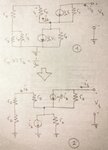
The result is well known to be Rout = \[\beta\]0*ro / 2, but when i´m performing the analysis i simply get stuck in the equations and cannot find a functional relation between my test output voltage and my test output current. My original small signal circuit, and after some typical assumptions, looks like this

And here is where i got stuck I can´t simply find how to relate the output voltage and current with respect to ib. Could you maybe provide some help how to solve it or where can I found a full explanation of this analysis. All the books and documents I´ve found state that "after doing the full analysis" the result is the one i mentioned before, but no detail can be found
Any help would be really appreciated!
Thanks a lot,
Regards,
Megaknaller
This is my first post and hope I can get some help/feedback about one question that has been annoying me since some time ago.
The problem is quite simple. I´m performing a full small signal analysis of the typical bipolar cascode as shown in the figure in order to calculate the output resistance of the current mirror

The result is well known to be Rout = \[\beta\]0*ro / 2, but when i´m performing the analysis i simply get stuck in the equations and cannot find a functional relation between my test output voltage and my test output current. My original small signal circuit, and after some typical assumptions, looks like this

And here is where i got stuck
Any help would be really appreciated!
Thanks a lot,
Regards,
Megaknaller

