kadavie
Newbie level 1
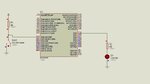
the calculator is supposed to take in a switch input by pressing the switch while rotating the leds on the pic then first it adds then it subtracts the code doesnt seem to be detecting my switch press, the code is as shown below:
#include <p16F887.inc>
__CONFIG _CONFIG1, _LVP_OFF & _FCMEN_OFF & _IESO_OFF & _BOR_OFF & _CPD_OFF & _CP_OFF & _MCLRE_OFF & _PWRTE_ON & _WDT_OFF & _INTRC_OSC_NOCLKOUT
__CONFIG _CONFIG2, _WRT_OFF & _BOR21V
ORG 0x00
GOTO START
cblock 0x20
COUNTER1 ; define a variable to hold a counter value
DELAY1
VALUE
endc
START:
CLRF COUNTER1 ;initialise value of variable
MOVLW B'00000100'
MOVWF DELAY1 ;initialise value of variable
CLRF VALUE ;initialise value of variable
BANKSEL ANSELH ;select bank3
CLRF ANSELH ; PortB pins are digitial (important as RB0 is switch)
BANKSEL TRISA ;select bank1
MOVLW 0xFF ; b'11111111'
MOVWF TRISA ; Make PortA all input
MOVLW 0x01 ; Bit one to work register
MOVWF TRISB ; Make RBO pin input (switch)
CLRF TRISD ; Make TRISD all output
BANKSEL PORTD ;select bank0
CLRF PORTD ;clear value in PORTD
BCF PIR1,0 ;Clears Flag.
MOVLW 0X31
MOVWF T1CON ;Enables Timer_1
CLRF TMR1H ; Clear timer1 counter
CLRF TMR1L ; Clear timer1 counter
INPUT1:
INCF COUNTER1 ; Increase counter value
MOVF COUNTER1,W ; move value in counter to work register
MOVWF PORTD ; move value in work register to PORTD register
BTFSS PORTB,0
GOTO NEXT_IN
CALL DELAY
MOVF PORTD,W
XORLW B'00000111'
BTFSS STATUS,Z
GOTO INPUT1
CLRF COUNTER1
GOTO INPUT1
NEXT_IN:
MOVLW 0Xff
MOVWF PORTD
CALL DELAY
MOVF PORTD,W
MOVWF VALUE
CLRF PORTD
CALL DELAY
INPUT2:
INCF COUNTER1 ; Increase counter value
MOVF COUNTER1,W ; move value in counter to work register
MOVWF PORTD ; move value in work register to PORTD register
BTFSS PORTB,0
GOTO ADDITION
CALL DELAY
MOVF PORTD,W
XORLW B'00000111'
BTFSS STATUS,Z
GOTO INPUT2
CLRF COUNTER1
GOTO INPUT2
ADDITION:
MOVF PORTD,W
ADDLW VALUE
MOVWF PORTD
CALL DELAY
CALL DELAY
CLRF PORTD
GOTO INPUT3
INPUT3:
INCF COUNTER1 ; Increase counter value
MOVF COUNTER1,W ; move value in counter to work register
MOVWF PORTD ; move value in work register to PORTD register
BTFSS PORTB,0
GOTO NEXT_IN_2
CALL DELAY
MOVF PORTD,W
MOVWF VALUE
XORLW B'00000111'
BTFSS STATUS,Z
GOTO INPUT3
CLRF COUNTER1
GOTO INPUT3
NEXT_IN_2:
MOVF PORTD,W
MOVWF VALUE
CLRF PORTD
INPUT4:
INCF COUNTER1 ; Increase counter value
MOVF COUNTER1,W ; move value in counter to work register
MOVWF PORTD ; move value in work register to PORTD register
BTFSS PORTB,0
GOTO SUBTRACTION
CALL DELAY
MOVF PORTD,W
XORLW B'00000111'
BTFSS STATUS,Z
GOTO INPUT4
CLRF COUNTER1
GOTO INPUT4
SUBTRACTION:
MOVF PORTD,W
ADDLW VALUE
MOVWF PORTD
CALL DELAY
CALL DELAY
CLRF PORTD
GOTO INPUT1
DELAY:
BTFSS PIR1,0 ;Skip if SET/1
GOTO DELAY
BCF PIR1,0
DECFSZ DELAY1
GOTO DELAY
MOVLW b'00000100'
MOVWF DELAY1
RETURN
END