Vermes
Advanced Member level 4
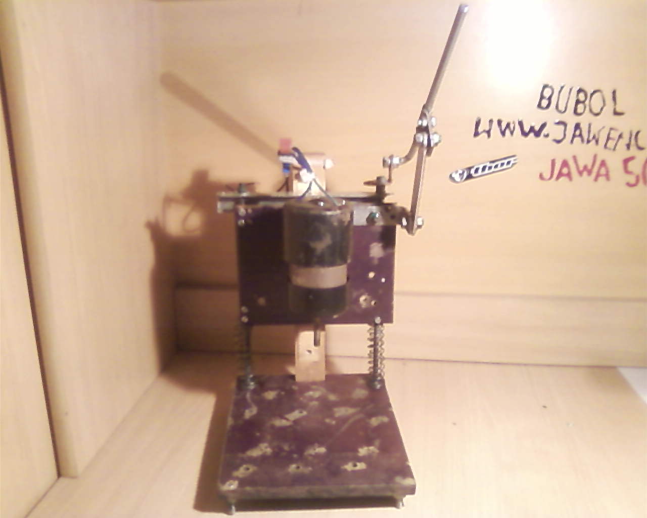
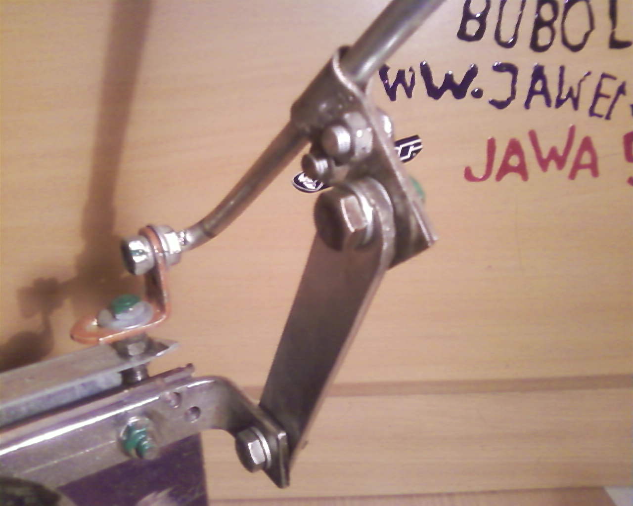
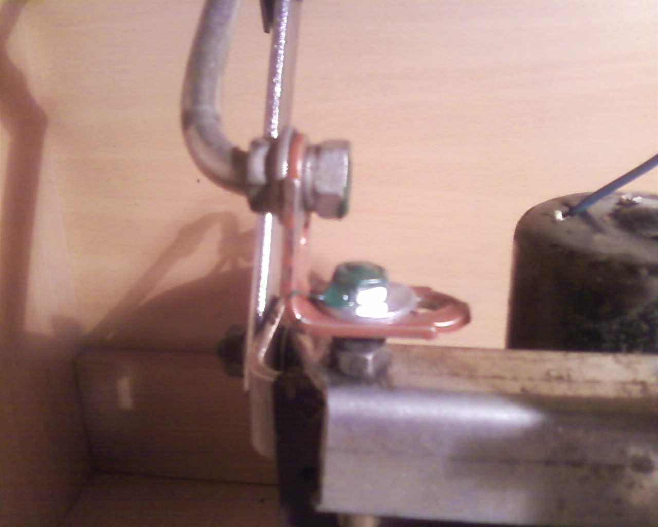
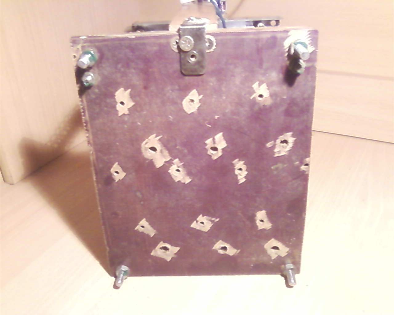
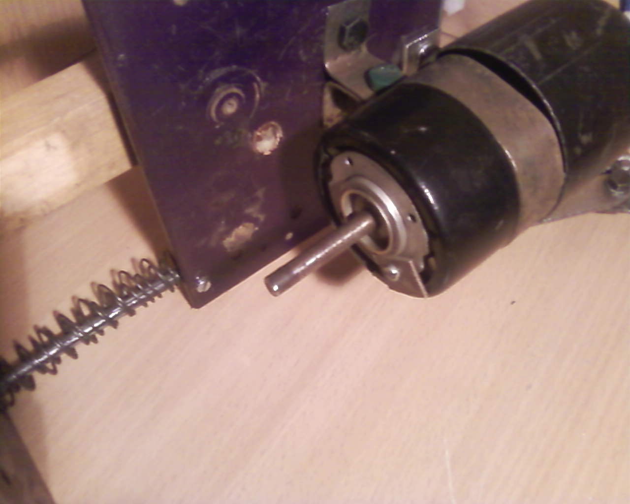
It is a small bench drill for PCB. Base was made of ebonite plate with a thickness of about 10mm. Rods for rails with a thickness of 5mm. Ebonite plate was also used as a base for mounting the engine. The engine is powered by 12V from 12V 12Ah accumulator. A piece of copper tube threaded in the middle with M6 die nut (with the same die nut the engine rotor was threaded). In addition, a steel bushing threaded in the middle (M4) was used.
The drill mount was made of an old cycling vent so it had to be re-threaded to the size of the M4, so it could be screwed to the bush. The vent had to be drilled with the drill you want to use. Then glue the vent with adhesive. You can also add a potentiometer to control the rotations.
Elements used:
- ebonite base for the rails and stands
- engine
- switch
- screws and nuts
- angles and springs


Link to original thread (useful attachment) – Wiertarka stołowa do PCB