Continue to Site

Welcome to EDAboard.com

Welcome to our site! EDAboard.com is an international Electronics Discussion Forum focused on EDA software, circuits, schematics, books, theory, papers, asic, pld, 8051, DSP, Network, RF, Analog Design, PCB, Service Manuals... and a whole lot more! To participate you need to register. Registration is free. Click here to register now.

battery equalizer system needed

Status
Not open for further replies.

yassin.kraouch

Advanced Member level 2
Joined
Jul 5, 2009
Messages
631
Helped
40
Reputation
80
Reaction score
40
Trophy points
1,308
Activity points
5,094
who have an idea of a system that equilibrate the charge between bettery in series ?
 

Well, if you had a duty factor that allowed it, the simplest is a periodic
full discharge (or whatever the cell allows). Then series charging current
imparts equal recharge (inefficiencies aside).

If you need individual cell charge control then you're probably looking at
a per-cell sense and overvoltage shunt which passes charge current at
"near cell charge voltage" (so you don't charge or discharge once full)
and at the endpoint all are topped up to roughly equal charge (just get
there at varying times along the way).

You could sense voltage or you could sense negative dV/dt as an
indication that incremental charge is going to temperature rise instead
of cell charging. Whatever you know about your cell attributes.
 

i didn't understand what do you mean by "periodic full discharge" ?
i don't know that there is an individual cell charge,
can you explain with a schematic please ?
 

what he probably means is this:
Eg NiMh,
so say let a cell full discharge be 1.0V

n cells,
discharge the battery ( n cells) to a voltage of n x 1.0V
so now (usually) all similarly discharged, and now recharge as normal.

However over time the cells individually may still vary. If you need the next level
of improved equalization, you need to be able to access each individual cell of
the battery.
 

This is a tough problem as a lead acid batteries with six cells in series may have one or two cells which may charge upto 2.20V and balance upto 2.40V .
This is a process of degradation in which the cell retention /conductivity /plate status needs to be ascertained .
There may be two things you can try .
a)Test out the acid density with a hydrometer .
b)See if the acid can be changed in the two cells .
c)You may need to remove /replace the old plates with new ones ...
 

Hi

I want to balance two 12V lead-acid batteries in series.
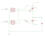
I designed a simple circuit that should take charge from battery "B" (12-24V) and charge battery "A" (0-12V)
It uses a capacitor that charges to 24V and then discharges over a 12V battery, if I repeat the process several times per second I can manage to get sufficient charge to flow from B to A.

I tested my concept and the capacitor goes up to 24 and down to 12 like a charm, but the "A" battery remains exactly the same (no voltage change).
The test I made uses a real 12V 7Ah battery for "A" and a power source for "B".
"B" was giving away 0.9A but "A" didn´t change.

Where did all that energy go?
thank you!
Captura de pantalla 2012-05-23 a la(s) 15.45.01.png
 

Battery charging/discharging equalizer often used for parallel connection of battery. At serial connection we dont have some problem like as in parallel connection.
 

@plusmartin

Where did all that energy go?

Let us discuss about charging/discharging a capasitor,
For example, using a voltage source, if you charge an empty capasitor with a series resistance of 100 ohms, then an energy will be lost in that 100 ohms. This lost energy is 50% of the total energy. If you use 10 ohms, the lost energy is still 50%. If you use 1 ohms, the lost energy is still 50%. It can be proved by calculus that the lost energy is independent of the resistance value. So according to calculus, If you use ZERO ohms, the lost energy must be still 50%. How ZERO ohms can consume energy? The SWITCH will consume the 50% energy mathmatically but secretly. This is also true during discharging.

So in your project 50% loss during charging and another 50% loss during discharging. So you will get 25% energy, and 75% energy will be lost in MOSFETS.
Thats why power switching circuits use INDUCTOR to transfer energy from one voltage level to another voltage level to get high efficiency like 90% or more.

Basically INDUCTOR works as energy carrier between two voltage levels.
And CAPASITOR works as energy carrier between two current levels.
 
Last edited:

ahsan:

so you are saying that using a capacitor to charge and discharge over a battery is inconvenient and i should better try a DC DC converter based on diodes and inductors?

I did`t quite understand why 50% loss on any resistance but i trust you.

In that case what circuit do you recommend to bring charge from one battery to another?
thanks
 

@plusmartin
so you are saying that using a capacitor to charge and discharge over a battery is inconvenient and i should better try a DC DC converter based on diodes and inductors?
Yes.
In that case what circuit do you recommend to bring charge from one battery to another?
Something like 12V(25% tolarence or more) to 12V battery charger circuit with input/output isolation(means,no common terminal between input 12v and output 12v)
Then you can easily charge a discharged battery with a charged battery, whatever their connection is.
 

thanks

I am looking for something that can be built in into a PCB, that is why I mentioned something like this: https://www.ti.com/lit/ds/symlink/tps40211.pdf

this steps 12V up to whatever voltage I need (in this case 24-28V) but only 700mA.
could there be something as simple as a boost circuit with 12V input that gives about 1, 2 or even 3, 4 Amps to variable voltage between 20 and 28V?
 

Battery charging/discharging equalizer often used for parallel connection of battery. At serial connection we dont have some problem like as in parallel connection.
I'm not aware of cell balancing circuits used in parallel connected batteries (except for Li-ion). It's also unusual for series connected lead acid and NiMH batteries, but mostly required for series connected Li-ion batteries..
 

@plusmartin
could there be something as simple as a boost circuit with 12V input that gives about 1, 2 or even 3, 4 Amps to variable voltage between 20 and 28V?
You can use MC34167. It can step down and also it can step up. Look at the circuit named "step-up/down converter" in the datasheet.
https://pdf1.alldatasheet.com/datasheet-pdf/view/12079/ONSEMI/MC34167.html
If you need better IC, I think you may have to open a thread. You will get lots of answers.
 

I'm not aware of cell balancing circuits used in parallel connected batteries (except for Li-ion). It's also unusual for series connected lead acid and NiMH batteries, but mostly required for series connected Li-ion batteries..

Its standard equipment in car with stronger amplifiers and two or more batteries. Also Mercedes in some serie of their car with two batteries have this implemented.
 

O.K, I see. I knew the said function as battery-cutoff relay. It's purpose is prevention of starter battery discharge and disconnection of auxilary battery during start. During charge, both batteries are usually parallel connected. But there may be more sophisticated models.

Interestingly I found scientific articles that claimed advantage of individual cell balancing for lead-acid batteries, similar to Li-ion.
 

Status
Not open for further replies.

Similar threads

Part and Inventory Search

Welcome to EDABoard.com

Sponsor

Back
Top