Continue to Site

Welcome to EDAboard.com

Welcome to our site! EDAboard.com is an international Electronics Discussion Forum focused on EDA software, circuits, schematics, books, theory, papers, asic, pld, 8051, DSP, Network, RF, Analog Design, PCB, Service Manuals... and a whole lot more! To participate you need to register. Registration is free. Click here to register now.

battery charging method from low torque generator

Status
Not open for further replies.

ElectronicsRookie

Member level 1
Member level 1
Joined
Oct 22, 2011
Messages
38
Helped
2
Reputation
4
Reaction score
2
Trophy points
1,288
Visit site
Activity points
1,614
Greetings,
I am attempting to come up with battery charger from a very weak generator source (like windmill etc). See fig.1 for reference BatteryCharger.jpeg V1 is the generator, Br1 is the
the bridge. SW1 and SW2 represents optoisolators as switches so that their turn off/on is controlled by external timer. The generator works fine when sees infinite
impedance. But when it is shorted, it stops. My generator source is typically of 3V and the battery I am attempting to charge is 2xAA or about 2.4V battery.
Since battery has low resistance which is equivalent to short, I attempt to use two switches to isolate short on generator. In other words, SW1 is on and SW2 is off
then c2 is charged, but battery is isolated. When SW1 is off and SW2 is on battery is charged and generator is isolated. The problem I have is that it works
fine with C2 of 2.2uF or below. When above 2.2uF the generator stops quickly depends how high is capacitance of C2. I do not understand how it affects
the generator. Is it related to impedance matching? Note that 2.2uF is too low for any useful charging current. Also adding high resistance resistor in series
with battery reduces usefull current too. I use timers with its own source as a tool to simulate charging sequence (to manipulate switching).
Can any one have any idea why I am stuck at 2.2uF?
Is there a way to beef up charging current (increase capacitance of C2 without stopping generator? I know I have lots of current generated before SW1 but I can't pull it all the way to battery.
Any other ideas will be greatly appreciated.
Thank you.
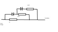
 

If we know about battery charging methotds and about constant current needs for charging of NiMh, and if we looks what time is needed to charge this batteries with standard and dedicated chargers, we can make easy conclusion about this.
 

If this is a "micro" power generator, you will be short of power so you don't want to waste any of it. At the moment, to get 1.5V on to the battery, you waste 4 X.8V across the forward biassed diode. i.e you have to generate 4.7V to get 1.5V!!. The first step is to replace the bridge with four GERMANIUM signal diodes (Vdrop ~.3V), now you can charge your batteries from 2.1V. Throw away the capacitors, what is happening is as the turbine builds up a voltage, the caps take more current, hence slowing the turbine down, but their voltage is still low, say 1V (not enough to charge the battery), if the turbine slows such that its blades screw action fall below 60% of the wind speed, they get inefficient. Now select a resistor to feed the batteries, this should allow the batteries to charge at the lowest wind speed. So now your battery will charge at the lowest wind speed. Now at higher wind speeds, you will have a higher voltage, but there will be more current available then you are using, so across your resistor put another germanium diode + resistor (say 1/3) the value of the first. By measuring the generators output voltage and the charging current you may find that a third diode + resistor will give you even more charge without overloading the turbines capacity. Points to note, the generators off load voltage should vary as wind speed. The optimum turbine rotor speed should be 2/3 wind speed. So measure AC voltage off load, measure on load* difference should be 1/3. Power in wind varies as wind speed cubed.
* on load voltage will be lower due to losses, so add 10% to compensate for this.
Frank
 

If this is a "micro" power generator, Frank

1)Yes it is micropower generator.
2)The bridge rectifier is self made. Since germanium diodes are hard to get, I used specific schottky diodes which gave me far less voltage drop than standard 0.8V drop. I also attempted with MOSFET however it gave me more voltage drop than schottky diodes at my disposal therefore I stick with schottky diodes.
3)I do not understand how capacitor can draw more current. They do not dissipate power, they store just like inductor.
4) Using the resistors will dissipate the useful power I am generating from generator.
5) The generator will slow down if I use low resistance resistor as a load, however current is high then. When I use high resistance resistor as a load , the generator works fine but current is very negligible.
6) Are you suggesting to put a resistor in series with battery? Schematic will be helpful
 

2. good
3. The problem is that at low wind speeds that caps charge up (like a short), taking a high current which stalls the turbine (you have to keep it turning). So as the turbine speeds it is constantly braked by the capacitor, because there is no limit to the current (and braking effect from the cap).
Have you done a Voff load & Von load, to see how you turbine/generator are doing?

The voltage without the load is measured to be 4.2V
Current generated when shorted is about 10mA.
Voltage with the load (70kohm resistor) is about 3.8V. Note that below 70k I have braking effect. Above 70k no braking effect. (It is measured and estimated). To put 70k resistor in series with battery will give me some microamps of current which will work but it will be useless for my purpose. I need minimum 1mA. If you look in fig. 1 again, its not C2 that gives me the problem. its the battery. Without the battery it runs fine. With the battery I have braking effect.

- - - Updated - - -

The voltage without the load is measured to be 4.2V
Current generated when shorted is about 10mA.
Voltage with the load (70kohm resistor) is about 3.8V. Note that below 70k I have braking effect. Above 70k no braking effect. (It is measured and estimated). To put 70k resistor in series with battery will give me some microamps of current which will work but it will be useless for my purpose. I need minimum 1mA. If you look in fig. 1 again, its not C2 that gives me the problem. its the battery. Without the battery it runs fine. With the battery I have braking effect.
Okay, it is still capacitor problem. I understand why it works without battery and does not work with battery. Without battery, caps are completely charged (once) and cannot discharge so it is like high resistor connected. With battery, capacitor discharge and charge again and this cycle induces braking effect on generator.
 

Stupid question :- is the battery dead flat?. its just that if your generator produces 4.2 V and a short circuit current of 10mA, this means that it has an output impedance of 420 ohms. But you are also saying that if you draw 3.8/70 mA = ~.057mA, the output voltage falls by (4.2 -3.8) .4V. This time the output impedance is .4/.057 K =~6K So under maximum power transfer theory, in the first case, it should be able to supply a max power to a similar load, i.e. 2.1 V at 5 mA. It could be that the battery (nominal voltage = 1.5V), presents a very low impedance when 2.1 V is presented to it. So there is something doing on which I do not understand about why the output impedance is changing so much.

Frank
 

Thanks Frank for following up on this. I will redo everything again in more detail and more carefully on weekend. Then I will post my results hopefully on Sunday if all will go accordingly.
 

Status
Not open for further replies.

Part and Inventory Search

Welcome to EDABoard.com

Sponsor

Back
Top