Deepon
Member level 1
This is a simple problem that has been haunting me from a very very long time.
I am explaining it with a simple example of an inverter. Lets see the outputof this simple Spice command:
* Waveform probing commands
.probe
.options probefilename="sedit.dat"
+ probesdbfile="Inverter2.sdb"
+ probetopmodule="inv"
* Main circuit: inv
M1 Out In Gnd Gnd NH L=2u W=.45u AD=66p PD=24u AS=66p PS=24u
M2 Out In Vdd Vdd PH L=.15u W=.9u AD=66p PD=24u AS=66p PS=24u
v3 In Gnd bit({0100101111} pw=100n on=5.0 off=0.0 rt=.01n ft=.01n delay=0 lt=10n ht=10n)
v4 Vdd Gnd 5.0
.tran 1n 400n
.print In Out
.include "dual.md"
* End of main circuit: inv
OUTPUT:

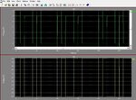
Now, notice the transitions Now,the Supply Vdd is fixed at 5v. Then how come during the transition it goes to 6v???
Moreover during low-high transition, it also goes as low as -1v. But how exactly can it happen?
Then I modified the width-length according to the dual.md model file and 2:1 ratio of PMOS:NMOS width,now the SPICE code is:
* Waveform probing commands
.probe
.options probefilename="sedit.dat"
+ probesdbfile="Inverter2.sdb"
+ probetopmodule="inv"
* Main circuit: inv
M1 Out In Gnd Gnd NH L=.15u W=.9u AD=66p PD=24u AS=66p PS=24u
M2 Out In Vdd Vdd PH L=.15u W=.45u AD=66p PD=24u AS=66p PS=24u
v3 In Gnd bit({0100101111} pw=100n on=5.0 off=0.0 rt=.01n ft=.01n delay=0 lt=10n ht=10n)
v4 Vdd Gnd 5.0
.tran 1n 400n
.print In Out
.include "dual.md"
* End of main circuit: inv
OUTPUT:

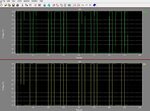
Now the output is fine. What I couldn't understand is that by modifying width/length, I simply varied the resistances and the o/p showed fine.
THEN WHAT IS THE SOURCE OF THAT EXTRA 1v (6v-5v) IN THE EARLIER OUTPUT???:!::!::sad:
I am explaining it with a simple example of an inverter. Lets see the outputof this simple Spice command:
* Waveform probing commands
.probe
.options probefilename="sedit.dat"
+ probesdbfile="Inverter2.sdb"
+ probetopmodule="inv"
* Main circuit: inv
M1 Out In Gnd Gnd NH L=2u W=.45u AD=66p PD=24u AS=66p PS=24u
M2 Out In Vdd Vdd PH L=.15u W=.9u AD=66p PD=24u AS=66p PS=24u
v3 In Gnd bit({0100101111} pw=100n on=5.0 off=0.0 rt=.01n ft=.01n delay=0 lt=10n ht=10n)
v4 Vdd Gnd 5.0
.tran 1n 400n
.print In Out
.include "dual.md"
* End of main circuit: inv
OUTPUT:

Now, notice the transitions Now,the Supply Vdd is fixed at 5v. Then how come during the transition it goes to 6v???
Moreover during low-high transition, it also goes as low as -1v. But how exactly can it happen?
Then I modified the width-length according to the dual.md model file and 2:1 ratio of PMOS:NMOS width,now the SPICE code is:
* Waveform probing commands
.probe
.options probefilename="sedit.dat"
+ probesdbfile="Inverter2.sdb"
+ probetopmodule="inv"
* Main circuit: inv
M1 Out In Gnd Gnd NH L=.15u W=.9u AD=66p PD=24u AS=66p PS=24u
M2 Out In Vdd Vdd PH L=.15u W=.45u AD=66p PD=24u AS=66p PS=24u
v3 In Gnd bit({0100101111} pw=100n on=5.0 off=0.0 rt=.01n ft=.01n delay=0 lt=10n ht=10n)
v4 Vdd Gnd 5.0
.tran 1n 400n
.print In Out
.include "dual.md"
* End of main circuit: inv
OUTPUT:

Now the output is fine. What I couldn't understand is that by modifying width/length, I simply varied the resistances and the o/p showed fine.
THEN WHAT IS THE SOURCE OF THAT EXTRA 1v (6v-5v) IN THE EARLIER OUTPUT???:!::!::sad: