Continue to Site

Welcome to EDAboard.com

Welcome to our site! EDAboard.com is an international Electronics Discussion Forum focused on EDA software, circuits, schematics, books, theory, papers, asic, pld, 8051, DSP, Network, RF, Analog Design, PCB, Service Manuals... and a whole lot more! To participate you need to register. Registration is free. Click here to register now.

Basic AM Receiver Design

Status
Not open for further replies.

talhanwaar

Newbie level 1
Newbie level 1
Joined
Jul 21, 2013
Messages
1
Helped
0
Reputation
0
Reaction score
0
Trophy points
1
Visit site
Activity points
10
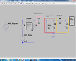
I made a basic AM receiver once. The received AM signal was very small, and it was difficult to amplify it as OpAmp amplified different frequencies differently and I didn't have much knowledge about OpAmps then. So I designed a circuit to detect the envelope first and then amplify the audio signal. Although it worked great at that time with some noise and I designed it myself, but now I doubt the functionality of the circuit. This is because the diode used for the envelope detection will always be on as the DC voltage was used to turn on the diode. So the diode will act as a wire for the AC signal. Also the value of the DC Bias voltage didn't matter. Can someone please clarify
AmReceiver.png
 

The schematic is almost correct. On the left, the AC source should be coupled to detector diode by another capacitor to make sure the DC circuit is not affected by AC source impedance.
If you noticed, the DC source has 0.7 V DC voltage which "opens" the detector diode into an optimum operating point, with the best detection features. This is called "DC biased" detector, and can respond well to weaker AC input signal compared to the same detector without DC bias.
Time constant on the detector R-C output determines detector response- a small time constant makes the detector response "peak" while a longer constant can be adjusted for a good response to modulated RF signals.
You can achieve an improvement if you replace the first R on the left with another diode, then you must set the DC bias to ~1.3...1.4 V as it opens both diodes.
Following the detector circuit, you can use either an opamp or any kind of audio amplifier to listen to AM signals.
 
Status
Not open for further replies.

Similar threads

Part and Inventory Search

Welcome to EDABoard.com

Sponsor

Back
Top