Continue to Site

Welcome to EDAboard.com

Welcome to our site! EDAboard.com is an international Electronics Discussion Forum focused on EDA software, circuits, schematics, books, theory, papers, asic, pld, 8051, DSP, Network, RF, Analog Design, PCB, Service Manuals... and a whole lot more! To participate you need to register. Registration is free. Click here to register now.

[SOLVED] Basic addition related (Digital electronics)

Status
Not open for further replies.

Div_01

Newbie level 4
Joined
Dec 20, 2021
Messages
7
Helped
0
Reputation
0
Reaction score
0
Trophy points
1
Activity points
65
Hi,
I have a question regarding addition in digital electronics, quite application specific.
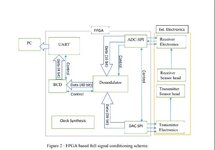
1)Let's say, I have 2 16-bit data coming from DAC and ADC to the demodulator that is 32 bits after multiplying. How many times is addition done to obtain a 40 bit data?
2) What would be the demodulator clock period for a 50MHz internal clock frequency and 32KHz sine wave? The answer that is obtained is 1320 as the demodulator clock period. But I am unable to understand how that number is obtained.
Please let me know if more details are required.
Can anyone explain me the procedure as well?

Thanks,
Divya
 
Last edited:

Hi,

I have no idea what you want to build or want to achieve.
A bit more description and a sketch would be very useful.

Is it some RF downsampling? Or a delta sigma application?

****
How can a 16 bit word come from an DAC? It maybe goes to the DAC ... but where do the two multiplication values come from?

When you multiply two 16 bit unsigned integers, then you get a 32 bit result.
When you multiply two signed 16 bit values, then you get a 31 bit (dynamic) result.
Thus I guess it's a good idea to tell how the 16 bits are defined.

Klaus
 

Can't read sense into the "period" value 1320 at first sight. What's the sine generation method, e.g. DDS + sine table?
 

Hi,

I have no idea what you want to build or want to achieve.
A bit more description and a sketch would be very useful.

Is it some RF downsampling? Or a delta sigma application?

****
How can a 16 bit word come from an DAC? It maybe goes to the DAC ... but where do the two multiplication values come from?

When you multiply two 16 bit unsigned integers, then you get a 32 bit result.
When you multiply two signed 16 bit values, then you get a 31 bit (dynamic) result.
Thus I guess it's a good idea to tell how the 16 bits are defined.

Klaus
Hi,
The bits are signed values. It is a delta sigma application.
The block diagram of the process is attached here

Divya
 

Attachments

  • Capture_1.JPG
    Capture_1.JPG
    44.5 KB · Views: 210

Can't read sense into the "period" value 1320 at first sight. What's the sine generation method, e.g. DDS + sine table?
Yes, the sine values are generated in MATLAB and a look up table is generated.
And the 1320 is the clock period, which I do not understand how the value was obtained. To create a demodulation clock, should there be a clock divider operation of sorts?
 

Attachments

  • Capture_2.JPG
    Capture_2.JPG
    50.8 KB · Views: 206

It is a delta sigma application.
Don't recognize a relation to delta sigma in the yet posted information.
The block diagram of the process is attached here
How is the block named "DAC" sending data? The only reasonable explanation is that there's a hidden signal generator in the block, sending both to DAC and modulator. Factor 1320 makes still no sense. You can either show the full 8811 module code or guesd on your own.
 

DAC8811 code :
Code:
library IEEE;
use IEEE.STD_LOGIC_1164.ALL;
use IEEE.NUMERIC_STD.ALL;

-- Uncomment the following library declaration if using
-- arithmetic functions with Signed or Unsigned values
--use IEEE.NUMERIC_STD.ALL;

-- Uncomment the following library declaration if instantiating
-- any Xilinx primitives in this code.
--library UNISIM;
--use UNISIM.VComponents.all;

entity DAC_8811_top is
            Port ( CLK : in STD_LOGIC;
            RST : in STD_LOGIC;
            DAC_MOSI : out STD_LOGIC;
            data_complete : out STD_LOGIC; -- reports to Demodulation block upon sending complete data (added later by varun)
            start_data : in STD_LOGIC; --  receives command from Demodulation block to send data.(added later by varun)
            DAC_SCK : out STD_LOGIC;
            DAC_CS : out STD_LOGIC;
            DEMOD_CLK : in STD_LOGIC; --- clock for demodulator data(added by varun LAter) (1320 demod clok period)
            TX_DATA : out  signed (16 downto 0)); --  data for demodulator block (added later by varun)
            end DAC_8811_top;

architecture Behavioral of DAC_8811_top is
        signal rdy,daccs,dacsck,dacmosi : std_logic;
        signal dacdata : unsigned(15 downto 0);
        signal pattern : unsigned(15 downto 0);
        type memory_type is array (0 to 24) of integer range 0 to 65535;  -- dac8811 will receive only 24 points but for demodulator 25 points will be available
        signal sine : memory_type :=( 32767,40609,47995,54496,59735,63406,65296,63406,59735,54496,47995,40609,32767,24924,17538,11037,5798,2129,238,2129,5798,11037,17538,24924,32767);
--        signal clk_div : std_logic := '0'; -- later added by varun
        type state_type is (send,stop); -- later added by varun
        signal state : state_type := send;  -- later added by varun


component DAC_SPI
               Port ( CLK : in STD_LOGIC;
                                RST : in STD_LOGIC;
                                DAC_DATA : in unsigned(15 downto 0);
                                DAC_MOSI : out STD_LOGIC;
                                DAC_SCK : out STD_LOGIC;
                                DAC_CS : out STD_LOGIC;
                                RDY : out STD_LOGIC);
        end component;

        
begin
U1_1 : DAC_SPI Port map ( CLK => CLK, RST => RST, DAC_MOSI => dacmosi, DAC_SCK => dacsck, DAC_CS => daccs, RDY => RDY, DAC_DATA => dacdata);


            process(RST,CLK,daccs,dacsck,dacmosi)
            variable temp : integer;
            variable i : integer range 0 to 24 := 0;
            begin
            if (RST='1') then
                DAC_MOSI <= '0';
                DAC_SCK <= '0';
                DAC_CS <= '1';
                    
            elsif falling_edge(CLK) then
                if (rdy = '1') then -- Check if first 32 bits is sent and proceed to the next
                    pattern <= to_unsigned(sine(i), 16); -- 16 bit value to change your output analog value, set your corresponding 16 bits digital value here.
                    i := i + 1;
                    if(i = 24) then
                        i := 0;
                    end if;
                    dacdata(15 downto 0) <= pattern;
                end if;
        end if;
        DAC_CS <= daccs;
        DAC_SCK <= dacsck;
        DAC_MOSI <= dacmosi;
end process;

process (CLK,DEMOD_CLK,start_data)
 variable k : integer range 0 to 25 := 0;
 begin
     if rising_edge(DEMOD_CLK) then
       if(start_data ='1')then
           case state is
                when send =>
                    data_complete <= '0';
                    TX_DATA <= to_signed(sine(k),17);
                 k := k+1;
                if (k = 25)then
                    state <= stop;
                    else
                     state <= send;
                    end if;
                when stop =>
                    k := 0;
                    TX_DATA <= (others => '0');
                    data_complete <= '1';
                    state <= send;
                end case;
        end if;
     end if;
end process;
    

end Behavioral;

DAC_SPI code :

Code:
library IEEE;
use IEEE.STD_LOGIC_1164.ALL;
use IEEE.NUMERIC_STD.ALL;
entity DAC_SPI is
Port ( CLK : in STD_LOGIC;
            RST : in STD_LOGIC;
            DAC_DATA : in unsigned(15 downto 0);
            DAC_MOSI : out STD_LOGIC;
            DAC_SCK : out STD_LOGIC;
            DAC_CS : out STD_LOGIC;
            RDY : out STD_LOGIC);
end DAC_SPI;

architecture behavioral of DAC_SPI is
    type state_type is (idle,ready,dummy,send,check);
    signal state : state_type;
    signal DAC_SEND : std_logic_vector(15 downto 0);
    signal clock_divide : std_logic:= '0';
    
    
    begin
    process(DAC_DATA)
        begin
            for i in 15 downto 0 loop
                DAC_SEND(i) <= DAC_DATA(15 - i); -- The data must be MSB first
            end loop;
    end process;


    process(CLK,RST)
        variable index : integer range 0 to 16 := 0;
         begin
         if (RST = '1') then
            index := 0;
        elsif falling_edge(CLK)then
            case state is
                when idle =>
                    DAC_SCK <= '0';
                    DAC_CS <= '1';
                    index := 0;
    --                DAC_MOSI <= '0';
                    RDY <= '1';
                    state <= ready;
                
                when ready =>
                    RDY <= '0';
                    DAC_CS <= '0';
    --                DAC_MOSI <= DAC_SEND(index);
                    DAC_SCK <= '0';
                    state <= dummy;
                when dummy =>
                    DAC_MOSI <= DAC_SEND(index);
                    state <= send;
                
                when send =>
                    DAC_SCK <= '1';
                    state <= check;
                    index := index + 1;
                
                when check =>
                    DAC_SCK <= '1';
                
                if (index = 16) then
                    state <= idle;
                else
                    state <= ready;
                end if;
            end case;
        end if;
end process;
end behavioral;
 

Status
Not open for further replies.

Part and Inventory Search

Welcome to EDABoard.com

Sponsor

Back
Top