Continue to Site

Welcome to EDAboard.com

Welcome to our site! EDAboard.com is an international Electronics Discussion Forum focused on EDA software, circuits, schematics, books, theory, papers, asic, pld, 8051, DSP, Network, RF, Analog Design, PCB, Service Manuals... and a whole lot more! To participate you need to register. Registration is free. Click here to register now.

Base current calculation for PNP transistor

Status
Not open for further replies.

Rosmawati Ismail

Junior Member level 1
Joined
Aug 14, 2010
Messages
18
Helped
1
Reputation
2
Reaction score
1
Trophy points
1,293
Location
Malaysia
Activity points
1,414
Hi everyone,
I am very new here.
Recently, I did a class project that involved in hardware designing.
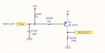
I am so silly I forget how to calculate base current for PNP transistor.
Anyone who willing to show me the way?
Actually I already did some calculation and now it is time for me to check the answer whether it is meet with others.

Here's the circuit:
 

Attachments

  • PNP.jpg
    PNP.jpg
    36.8 KB · Views: 267

When your input is low you have 5V across R2000 and the transistor BE junction. Assuming you lose 0.7V across the base-emitter junction, you have 4.3V across R2000. So, around 63uA.

Keith.
 
Hi Keith,
Thank you for your reply.
I assumed you use base current formula same as mine which is:

IB = (Vinput - VBE) / RB

What's different is instead of using 5V, I used 12V as Vinput.
Would you brief a little why u're not using 12V? And if the load is to trigger microcontroller input pin to high level, does the total amount base current is enough to trigger the BC 857S transistor?

Any reply would be appreciated.
Thank you.
 
  • Like
Reactions: an218

    an218

    Points: 2
    Helpful Answer Positive Rating
I use 5V, because that is the voltage driving the transistor ON. The 12V doesn't turn the transistor ON - it reverse biases the base-emitter junction. The 12V could cause reverse base-emitter junction breakdown - most transistors are only rated around 5V, for reverse base-emitter voltage. It shouldn't damage anything due to the series resistor but it is not good design practice.

The base current will be more than enough to switch the micro pin.

Keith
 

Which design is better?
With pull up o without pull up resistor? I have been told by my seniors that it is better to put any pull up/down resistor in case of protection.
 

I agree it is a good idea to have a resistor to ensure the transistor turns off but I would put it directly across the base-emitter - not to 12V.

Keith
 

I see. Now I got what you meant.
Thank you very much for sharing the diagram. Will be a very useful reference for next time.

D1N4148 is what for? Protection?

For the 2nd diagram, I believe the input voltage must be HIGH. Am I correct?

Rose.
 

The diode is to protect the base-emitter from more than 5V reverse voltage when the input is at 12V.

For the second circuit the input need to be pulled to 12V (or 5V) for the transistor to switch. It may not suit your signal source.

Keith
 
That is why.

So I think I'll stick with the 1st one.
By the way, this is a bit out of context. But, do you know about microphone/speaker stuff?

I have problems connecting them to my GSM module.

Thank you.
 

That is why.

So I think I'll stick with the 1st one.
By the way, this is a bit out of context. But, do you know about microphone/speaker stuff?

I have problems connecting them to my GSM module.

Thank you.

It is probably best to start a new thread with a new title otherwise people who know about microphones won't spot the thread (entitled "Base current calculation ...").

Keith.
 
Status
Not open for further replies.

Part and Inventory Search

Welcome to EDABoard.com

Sponsor

Back
Top