Continue to Site

Welcome to EDAboard.com

Welcome to our site! EDAboard.com is an international Electronics Discussion Forum focused on EDA software, circuits, schematics, books, theory, papers, asic, pld, 8051, DSP, Network, RF, Analog Design, PCB, Service Manuals... and a whole lot more! To participate you need to register. Registration is free. Click here to register now.

Bandpassfilter amplifer

Status
Not open for further replies.

JamesGon

Junior Member level 1
Joined
Sep 8, 2017
Messages
18
Helped
0
Reputation
0
Reaction score
0
Trophy points
1
Activity points
157
Hi.
I am designing a Bandpass transimpedance amplifier. But I unfortunately I have trouble understanding some basic stuf. The circuit I am planning to use is shown below. It is a reversed biased photodiodes.

I know that the lower and upper frequencies in a active bandpassfilter is found by the following equations:
flow = 1/2piR2C2 (highpass) and fhigh = 1/2piR1C1 (lowpass). I want my flow to 600kHz and fhigh to at 700kHz, so a 100kHz bandwidth. But I am not getting close to this, when doing a AC-sweep. Can someone tell me, what I am doing wrong.
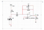
forumbandpasstransimpedance.PNG
 

Presumed the photo diodes can be assumed as current source with sufficient low capacitance (<< 35 pF), the circuit does have the said high-pass/low-pass characteristic. But you shouldn't expect significant selectivity from the first order filter.

Better specify the intended filter characteristic with pass- and stop-band parameters and determine the required filter topology and order.
 

Most opamps do not have much gain at such high frequencies.
The first-order filters are so simple that their corners and slopes are very gradual and affect each other.
 

Hi,

I agree.

Maybe you should look for a higher Q (resonance) circuit.

Klaus
 

HI
Okay, I am confused. Can you guys elaborate that with an example or proper literature?
By the way, what is the gain? Usually in a tranimpedance amplifer you have A/V gain. Is the gain here decided by R1 and R2.
And How do you do a proper simulation – that simulates the current pulses generated by the photodiode?

Best regards
 

Hi,

read about passive or active bandpass filters with Q>1
Did you try: https://en.wikipedia.org/wiki/Band-pass_filter

Gain:
the gain in V/A of a transimpedance amplifier is determined by the feedback resistor R1,
For AC: the feedback impedance: R1 || C1.

But in your case you have additional circuitry: R2, C2 .. for sure they influence the gain, too.

For sure you can all do this with just one OPAMP, but maybe it´s easier and more obvious if you divide it in a true TIA and an extra OPAMP for the bandpass.

It depends if you do this just for fun or for a research, or if you design a mass product.

Klaus
 

Status
Not open for further replies.

Similar threads

Part and Inventory Search

Welcome to EDABoard.com

Sponsor

Back
Top