Vermes
Advanced Member level 4
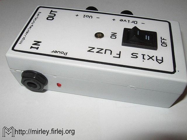
Axis Fuzz is a silicone version of a well known effect, which was once designed for Jimi Hendrix. There are many version of that simple system on the Internet.
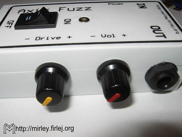
Transistors determine the obtained sound. Original Fuzz was built on germanium transistors, but nowadays it is difficult to get such elements. Testing different transistors, you can match the tone for your needs, however making two identical systems is virtually impossible. The system was equipped with automatic power switch, after inserting the plug with input signal (IN), Fuzz automatically switches on. Two-position switch mounted in the housing allows you to switch off the effect without changing the connection of the cables. Output socket is then plugged directly to the input socket without the signal path.
Scheme:
G2 socket (Jack 6,3mm, mono) allows you to connect the signal from guitar. Its additonal connectors are the power switch at the same time. It can happen with help of transistors T1 (BC327) and T2 (BC546) and resistors R1 (4,7M), R2 (10k) and R3 (10k). If the plug is dosconnected, base of transistor T2 is shorted to the ground and small current flows through resistor R1. Transistor T1 is then cut off and the whole system does not work. Inserting the plug into the socket G2 causes enabling the transistors T2 and T1, and thus starting the system. Switch J1 gives to the output socket G1, or signal from Fuzz output, or directly from the input socket G2.
Resistor R11 (2,2M) and C1 (100nF) and C7 (470pF) form the input filter. Resistors R6 (180k), R7 (820k) and R12 (680k) polarize the base of transistor T3 (2N3906). Components R8 (220R), R9 (47k) and capacitors C2 (100nF) and C4 (22uF) with potentiometer P1 (2k) are the circuit of forming the signal. Changing the position of slider P1 into the side of ground results in enlarging the effect. Output signal is collected from the divider R4 (10k), R10 (22k) by capacitor C5 (2,2uF). Potentiometer P2 (50k) is used for the volume control.
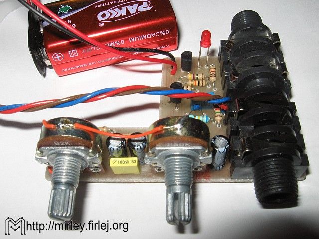
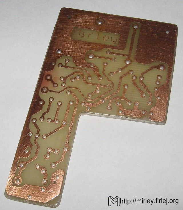
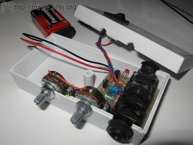
Mounting the system is simple, because it does not have any SMD components. The board should be cut in form shown in the pictures, because that allows you to fit all elements with 9V battery in a small housing Z27A. Firstly, solder one jumper, which is below potentiometer P2, then all the resistors and solid capacitors. Solder pieces of single cables in place of switch J1 – they should be twisted later (as shown in the pictures) and soldered to the switch in the housing. Diode D1 should be soldered vertically on long pins. After mounting all elements in the housing, the diode D1 can be 90 degrees angled and put in previously drilled hole in the wall of the housing. Electrolytic capacitors, input and output connectors should be placed in the end. A „tadpole” for the 9V battery should be soldered into the connector for the battery (BAT1).
For aesthetic reasons, stick the front panel after placing everything in the housing. The front panel can be printed on the self-adhesive paper and covered with self-adhesive foil.
Pictures:
More information can be found at: LINK.
Link to original thread (useful attachment) – Axis Fuzz - Efekt gitarowy