ankitbende
Newbie level 4
Hello everyone,
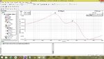
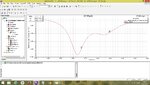
I am trying to design a circularly polarized patch antenna using probe feed in HFSS. The problem I am facing is the impedance matching of the two orthogonal frequencies generated for circular polarization. I am getting high capacitance for one of the frequency separated by few MHz. Please give me suggestion to nullify this capacitive effect and achieve impedance matching for both the frequencies separated by a little.
I am able to achieve good impedance matching when I increase the outer diameter of coaxial feed in hfss but I have to use standard dimensions of coaxial connector as available in market. Please suggest some method to decrease the capacitance.