Continue to Site

Welcome to EDAboard.com

Welcome to our site! EDAboard.com is an international Electronics Discussion Forum focused on EDA software, circuits, schematics, books, theory, papers, asic, pld, 8051, DSP, Network, RF, Analog Design, PCB, Service Manuals... and a whole lot more! To participate you need to register. Registration is free. Click here to register now.

AWR Oscillator Nonlinear Analysis Error with OSCAPROBE

Status
Not open for further replies.

turkmenes

Newbie level 2
Newbie level 2
Joined
Mar 13, 2014
Messages
2
Helped
0
Reputation
0
Reaction score
0
Trophy points
1
Visit site
Activity points
16
Hi there,

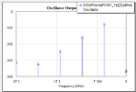
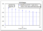
I am designing 10 Ghz Oscillator with microstrip resonator. I have problems about nonlinear analysis. I use OSCAPROBE for harmonic balance analysis. But Pharm spectrum shows negative frequencies range.

-Schematic
schematic.png

-Resonator S Paramater
resonator.png

-Linear Analysis Results
linear.analysis.png

-Nonlinear Analysis Results
pharm.png[/ATTACH]

=> I tried set up OSCAPROBE settings, but i seen different errors such as convergence failed, failed to find start-up conditions vs..

thank you!
 
Last edited:

The frequency is not negative, your oscillator doesn't work.That's why the output level is too low and of course it shows negative numbers in dBm (remember dBm is a logarithmic measurement, the levels which are smaller than 1mW are always negative in dBm).
Have you ever checked the input impedance of the active part ?? For start-up conditions,
They should be satisfied
Ga+Gp<0
Ba+Bp=0
Also.. What is for R1=50 Ohm ? You should connect the other port of the resonator directly to the GND. Otherwise you would been increase the series resistance resulting low Q factor.

Thanks. I designed the resonator with two port. If there isn't 50 ohm between gnd and resonator, resonator doesn't work correctly.

I'm new to awr and this is my first microwave active circuit. I dont know Ga+Gp<0 and Ba+Bp=0. What are they?
 
Last edited:

Thanks. I designed the resonator with two port. If there isn't 50 ohm between gnd and resonator, resonator doesn't work correctly.

I'm new to awr and this is my first microwave active circuit. I dont know Ga+Gp<0 and Ba+Bp=0. What are they?
First, you should design one port resonator not two port.The topology of your VCO needs one single port resonator.
Second, read something about the oscillators and theory before involving into simulations.For instance "High Frequency Oscillators Design for Integrated Transceivers" J.Van der Tang, Dieter Kasperkovitz,Arthur van Roermund
Ga:Active parts conductance
Ba:Active parts suceptance
Gp:passive parts conductance
Bp:passive parts suceptance.

Oscillators are true complicated systems and they have to be very carefully understood their characteristics and fundamentals.
 

Status
Not open for further replies.

Part and Inventory Search

Welcome to EDABoard.com

Sponsor

Back
Top