Continue to Site

Welcome to EDAboard.com

Welcome to our site! EDAboard.com is an international Electronics Discussion Forum focused on EDA software, circuits, schematics, books, theory, papers, asic, pld, 8051, DSP, Network, RF, Analog Design, PCB, Service Manuals... and a whole lot more! To participate you need to register. Registration is free. Click here to register now.

Assist me in designing a high current variable voltage switch mode power supply

Status
Not open for further replies.

RCAnderson

Newbie level 3
Joined
Nov 8, 2011
Messages
4
Helped
0
Reputation
0
Reaction score
0
Trophy points
1,281
Activity points
1,332
Basically, I felt like making myself a little desk PSU.

I wish to design something that is capable of putting out probably 20A+ at a range of DC voltages, varying from 0-50V (From a 12VDC supply)

Only issue, is that I've never done anything with SMPSUs, so I don't really know where to start. I know there are ICs that are meant to control everything, and all that's needed are a few MOSFETs, caps, inductors & resistors, however I don't know which ICs are good, or even how your meant to wire them up.

Any help you can give would be good, anything from an intro into SMPSUs, to a step by step guide of how to make one that will do what I want (Including exact components)

So, can anyone help me?
 

You need to deliver 1KW power and your output range is both above and below input voltage. Thus you need buck-boost kind of topology. I would suggest first select a topology and then go select the appropriate controller IC.
 

hello deepone,
In yours first diagram left u showed the main supply but in secfond right no main is shown,would u like to clarify plz.Thanks
 

Thanks all.

First of all, DeepOne, the first circuit you showed, what's the source of this? Are there any output traces etc to show how well it operates? Also, is there a simulator that would simulate that circuit well, so I can see how it performs?

Does anyone know about Linear Technology parts? I've had a few people say they're good, and they're simulator is very accurate, so if anyone knows anything about those, that would also be nice to consider.

atripathi: Are you meaning I should choose either Buck, or Boost? As I know there are controllers that will do both, as and when required. Only issue is, from what I've found, they're usually a fixed output, capable of outputting that voltage with a range of input voltages, but I want to reverse this.
 

Okay if that's your goal you should slow down because you've got a long ways to go. Aside from the normal amount of engineering that goes into a SMPS, a variable voltage SMPS is generally much more complicated because it has to maintain efficiency over a broad range of loads and output settings. It's not straightforward at all.
Does anyone know about Linear Technology parts? I've had a few people say they're good, and they're simulator is very accurate, so if anyone knows anything about those, that would also be nice to consider.
I've dealt with LT parts a lot (and LTspice). They're often very good, well documented, but they do have issues sometimes. But I doubt they have any parts that are suitable for you. Most of their controllers are specialized for specific applications, while you have a very broad operating range. You should look into more generalized PWM controllers, like the UC38xx family.

Here's a few tips you should consider:
  1. 20A is a huge amount of current for a PSU. Lower it to around 3-5A. Trust me, it will make things much easier (and lest costly). Also consider lowering your output voltage range to 30V max, for the same reasons. If you can get those lower specs with a first try, then stepping up the power from there won't be too hard.
  2. The fact that you want to operate from a 12V source and have outputs above and below that means you'll have to do one of two things: 1) Use a boost-buck dertived supply, which will be tricky to control, or 2) Use a transformer based converter, like a flyback or push pull. Getting the right transformer is the only hard part of this. After that it should be much easier to get it working.
  3. Most common benchtop PSUs are based on discontinuous mode, multi output flyback converters (which operate off line from a ~350V bus). In general this type of converter has poor characteristics, but is is possible the easiest topology to control over a large operating range. If you are new to SMPS, then I recommend you follow that example.
  4. Even if you take all my advice to make things easier, you're still looking at a huge amount of material to understand. Prepare for a long haul.

Keep in mind this applies to an actually good design with good efficiency, transient response, fault protection... if you neglect those things then it will become much easier... but then what's the point?
 

hello, ch wazir.
In the second right diagram car battery serves as power supply. But this simply example of the pwm regulation of the current and voltages (from german site, no remember where has found).

Hi, RCAnderson.
the first circuit you showed, what's the source of this?
sorry, sourse of this circuit is in old journal "Radio". So, no output traces, no sim. But I have done pair of such schemes on powers before 300W and think that possible to accelerate it before kiloWatt.
In particular - transistor driver orderly pulls 2 -3 power fets in parallel.
 

Thanks for the additional info everyone.

I just had a thought, would it be much easier if I ran the whole thing off a higher voltage? As I could make an AC rectifier myself to use with it, and run it off 230VDC instead. (Only reason I was going to do it off 12V, was I have a powerful 12V supply already, so I was thinking it would be easier, but if it's not, there's no point)
 

After a bit of thought, and looking around, I think I've changed my mind on the requirements. I would still like similar current capabilities, however it's ok for the voltage required to drop to around 1-24V.

From this, however, I've come across a chip from LT (this one) which seems to do all that, only other issue with that, is I would need a higher input voltage, however I don't see this being too much of an issue, as if I build it to run direct from the mains, I could get a transformer to turn 230VAC into ~50VAC, then rectify that to use as the supply.

EDIT: After looking into this further, it seems like it would be quite a bit more expensive to do it this way, as it doesn't seem to be very easy/cheap to obtain a 230V-50V transformer. Would it be possible to run the whole thing (with the IC linked above running off 5V) off 230VDC, as long as I switch the rest of the components out for different ones that have a higher voltage rating?
 
Last edited:

hey engineers i'm a comm department i don't know much about power electronics so i was asking what is the parameters that i need to know when charging a 12 v dc 70A battery. and is there any one here knows how to drive high current without using transformer what i mean is a i want a small output voltage with high current about 19v dc /5A for example
or higher ampere i need to know the concept in driving high current without using very big transformers and so on
thanks all
 

Okay if that's your goal you should slow down because you've got a long ways to go. Aside from the normal amount of engineering that goes into a SMPS, a variable voltage SMPS is generally much more complicated because it has to maintain efficiency over a broad range of loads and output settings. It's not straightforward at all.
I've dealt with LT parts a lot (and LTspice). They're often very good, well documented, but they do have issues sometimes. But I doubt they have any parts that are suitable for you. Most of their controllers are specialized for specific applications, while you have a very broad operating range. You should look into more generalized PWM controllers, like the UC38xx family.

Here's a few tips you should consider:
  1. 20A is a huge amount of current for a PSU. Lower it to around 3-5A. Trust me, it will make things much easier (and lest costly). Also consider lowering your output voltage range to 30V max, for the same reasons. If you can get those lower specs with a first try, then stepping up the power from there won't be too hard.
  2. The fact that you want to operate from a 12V source and have outputs above and below that means you'll have to do one of two things: 1) Use a boost-buck dertived supply, which will be tricky to control, or 2) Use a transformer based converter, like a flyback or push pull. Getting the right transformer is the only hard part of this. After that it should be much easier to get it working.
  3. Most common benchtop PSUs are based on discontinuous mode, multi output flyback converters (which operate off line from a ~350V bus). In general this type of converter has poor characteristics, but is is possible the easiest topology to control over a large operating range. If you are new to SMPS, then I recommend you follow that example.
  4. Even if you take all my advice to make things easier, you're still looking at a huge amount of material to understand. Prepare for a long haul.

Keep in mind this applies to an actually good design with good efficiency, transient response, fault protection... if you neglect those things then it will become much easier... but then what's the point?

Hi guys,

I am considering a very similar project. A versatile bench-top power supply is an essential tool for any electronics lab in my opinion, and I would really like to build my own since it is the perfect opportunity to learn hands-on and of-the-shelf supplies for this application are a bit expensive.

I scavenged a massive 300VA toroidal transformer which turns our Australian mains (230V) into 36V (51Vrms after rectification to dc) @ 8.33 amps, and would like to turn this into a variable voltage SMPS (say 5 to 50V).

I've done a bit of research and the best solution looks to be this: TPS40170. The only problem is, it doesn't look like this IC was meant for varying voltages on the fly i.e. you're supposed to pick one voltage somewhere between 5-95% duty cycle, design the circuit accordingly and stick with that single voltage. The circuit only changes slightly though, so I'm planning to do a bit of prototyping; design a circuit for 50% duty cycle (around 24.5V), then vary the resistance with a potentiometer on R10 in the circuit, and hopefully this will just vary the duty cycle. I'm guessing it won't be very stable though.

Here is my prototyping/experiment circuit:
View attachment Vout24.bmp

Notice the little changes if i want the output to be around 45V (95% duty cycle):
View attachment Vout45.bmp
Any thoughts on this appreciated very muchly, thanks :grin:
 

**broken link removed**


Also see whole web site, its very useful.
Thanks tpetar, almost exactly what I want, but maybe a bit too complicated for my limited knowledge in the field :???:. It will take me quite a while to analyse
 

I scavenged a massive 300VA toroidal transformer which turns our Australian mains (230V) into 36V (51Vrms after rectification to dc) @ 8.33 amps, and would like to turn this into a variable voltage SMPS (say 5 to 50V).

I've done a bit of research and the best solution looks to be this: TPS40170. The only problem is, it doesn't look like this IC was meant for varying voltages on the fly i.e. you're supposed to pick one voltage somewhere between 5-95% duty cycle, design the circuit accordingly and stick with that single voltage. The circuit only changes slightly though, so I'm planning to do a bit of prototyping; design a circuit for 50% duty cycle (around 24.5V), then vary the resistance with a potentiometer on R10 in the circuit, and hopefully this will just vary the duty cycle. I'm guessing it won't be very stable though.

Here is my prototyping/experiment circuit:
Vout24.bmp

Notice the little changes if i want the output to be around 45V (95% duty cycle):
Vout45.bmp
Any thoughts on this appreciated very muchly, thanks

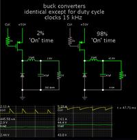
Since I enjoy running simulations (and have time for it)...

I constructed a simple buck converter using your parameters.

Screenshot:


Your goals are possible. By adjusting between 2% and 98% duty cycle, you can obtain a wide range of volt levels at the load.

The operating frequency was adjusted so that the coil is running well into continuous conduction mode at 45V with heavy load. Notice that current through the coil will eventually reach a plateau if the switch is left 'On' for a long enough time. Available current will be limited by the summed resistance in components. If you wish to increase available current, you may need to assemble 2 or more mosfets in parallel.

At least this is how the theoretical simulation plays out.
 

Visit www.bcae1.com and goto to the chapter of the switching power supply, i mean this guy as even explained the diferent toroid materials, dissected the tl594, it cover all the basics. just go there and dive!!!!

ps.. sorry the previous bad url...
 

Hi there! There are tons of **broken link removed** in switch mode available in the market, so I think you should just buy one. I’d recommend a Seasonic 80Plus Power Supply M12II 620 Or a . Cooler Master Elite 460W. They both have a switch mode. I have the cooler master. And it work really well. Hope that helps.
 

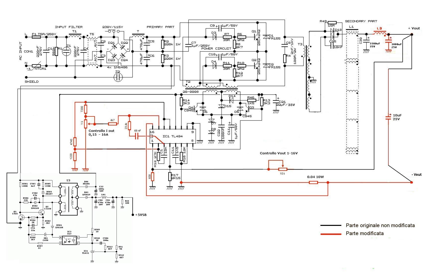
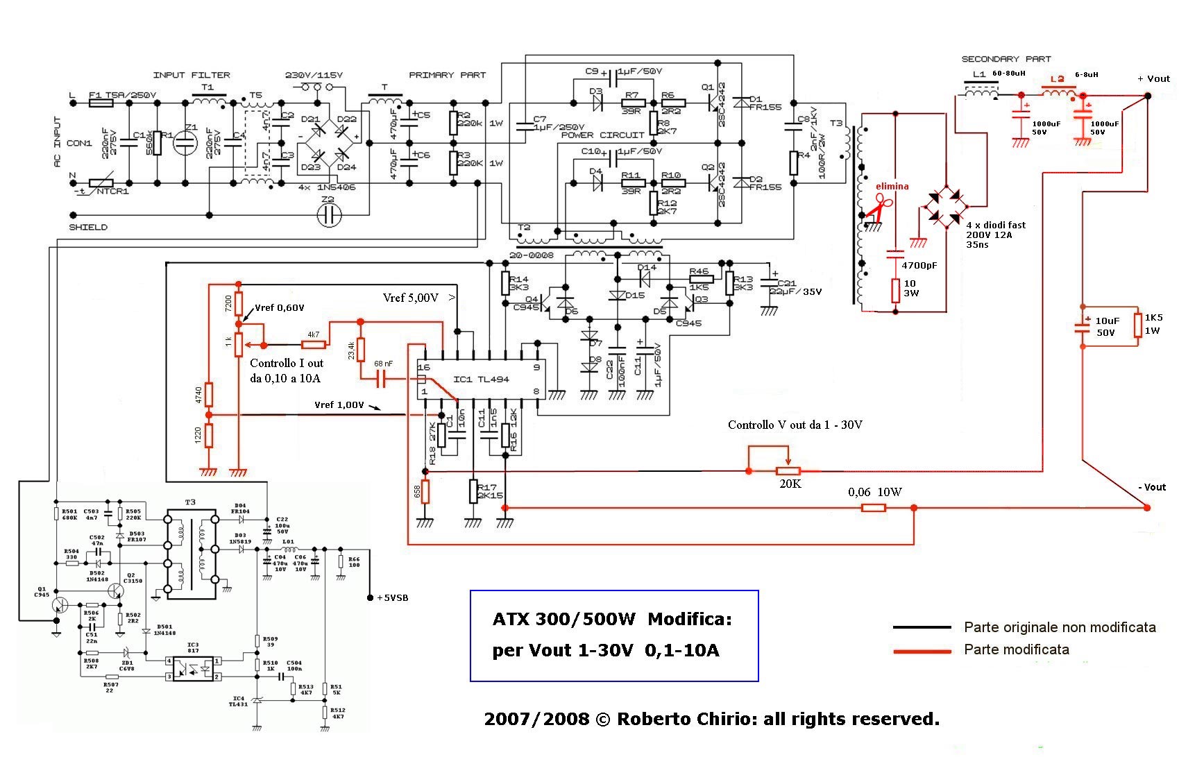
If we are talking about ATX PSU
How to Convert a Computer ATX Power Supply
to a Laboratory Power Supply

atx_schema_03.jpg

atx_schema_30v_2008_01.jpg
 
Status
Not open for further replies.

Similar threads

Part and Inventory Search

Welcome to EDABoard.com

Sponsor

Back
Top