Continue to Site

Welcome to EDAboard.com

Welcome to our site! EDAboard.com is an international Electronics Discussion Forum focused on EDA software, circuits, schematics, books, theory, papers, asic, pld, 8051, DSP, Network, RF, Analog Design, PCB, Service Manuals... and a whole lot more! To participate you need to register. Registration is free. Click here to register now.

[ASK] Band Pass Filter Transmission Line Effect 145 MHz

Status
Not open for further replies.

rhyando

Newbie level 4
Joined
Dec 28, 2010
Messages
6
Helped
0
Reputation
0
Reaction score
0
Trophy points
1,281
Activity points
1,323
Hello.

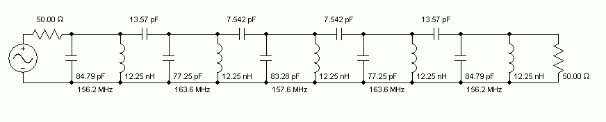
I want to design Bandpass Filter with Specification :

f = 145.95 MHz
BW = 20 MHz
Type = Butterworth
Orde = 5

I have made the design and i have attached it here.

BPF.JPG

I want to ask the effect of transmission line connecting each lumped elements. Does it effect the frequency response of my bandpass filter ?
Can i simulate transmission line effect in ADS ? HOW ?
Can i just design the PCB with altium and made bandpass filter with it ?
 

At 160 MHz, you don't need to worry about transmission line. But you do need to worry about your layout as one inductor is only 3-4 nH, while the other is above 600 nH. You need to make circuit transformation to make it realizable. I don't see how do you build the filter with your design!
 

If you change your order down to 4 or up to 6, you may have more reliable components..
Or change your approximation such as Chebychev.. etc.. or Cauer..
Because parts have extreme values and litlle tolerances will shift your filter response much... did you do sensitivity analysis ??
 

If you change your order down to 4 or up to 6, you may have more reliable components..
Or change your approximation such as Chebychev.. etc.. or Cauer..
I fear, this modifications won't change the wide range of inductance values. Sensitivity is another thing and not necessarily related to it. It can be generally expected lower with low Q (e.g. Butterworth) design.

But there are alternative filter structures as the coupled resonator, that achieves more comfortable component values, at cost of four additional capacitors:

 
At 160 MHz, you don't need to worry about transmission line. But you do need to worry about your layout as one inductor is only 3-4 nH, while the other is above 600 nH. You need to make circuit transformation to make it realizable. I don't see how do you build the filter with your design!

i use power loss raio charachteristic to build the bandpass filter in borowick but the result that i get is an extreme value like you said. any other suggestion of method to design bandpass filter ?

---------- Post added at 05:47 ---------- Previous post was at 05:45 ----------

I fear, this modifications won't change the wide range of inductance values. Sensitivity is another thing and not necessarily related to it. It can be generally expected lower with low Q (e.g. Butterworth) design.

But there are alternative filter structures as the coupled resonator, that achieves more comfortable component values, at cost of four additional capacitors:


can you told me the method to design bandpass filter that you suggest ?
 

Status
Not open for further replies.

Part and Inventory Search

Welcome to EDABoard.com

Sponsor

Back
Top