Continue to Site

Welcome to EDAboard.com

Welcome to our site! EDAboard.com is an international Electronics Discussion Forum focused on EDA software, circuits, schematics, books, theory, papers, asic, pld, 8051, DSP, Network, RF, Analog Design, PCB, Service Manuals... and a whole lot more! To participate you need to register. Registration is free. Click here to register now.

Anyone with antenna simulator software ?

Status
Not open for further replies.

Externet

Advanced Member level 2
Joined
Jan 29, 2004
Messages
616
Helped
28
Reputation
58
Reaction score
30
Trophy points
1,308
Location
Mideast US
Visit site
Activity points
6,158
Hi.
Please, can someone capable of simulating / evaluating a theorical antenna show the results, characteristics and impedance plotting from 50 MHz to 1000 MHz for a 78 cm diameter loop with 1mm conductor ?
 

OK. Seems am asking a too lunatic thing...

Just wanted to learn what would be the behavior and characteristics of a loop antenna working well out of its intended range.

Is there any magnetic loop antenna on-line calculator (or for Linux) that you can suggest ?
 

the free NEC2 should do this for you. I use 4nec2 myself and I think it even comes with some loop examples installed.
 
  • Like
Reactions: FvM

    FvM

    Points: 2
    Helpful Answer Positive Rating
The presented loop acts only at low frequencies as magnetic loop antenna. Over most of the frequency range it has more similarities with a folded dipole. The current distribution is far from being uniform, the input impedance is non-monotonically varying with multiple resonances over the frequency range.

No job for a simple "calculator", rather a full-featured EM solver.
 

Thanks.
Yes, those multiple resonances are the ones I would like to see plotted. No access to a full featured EM solver :-(

A simple on-line calculator found shows the attachment, for the unusually large circumference :
 

Attachments

  • Loop.png
    Loop.png
    87 KB · Views: 113

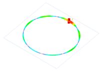
The current distribution is far from being uniform, the input impedance is non-monotonically varying with multiple resonances over the frequency range.

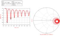
Correct. This is the input impedance into the loop


and we can see the various current minima/maxima on the loop at 500MHz


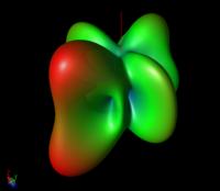
which lead to a rather complex radiation pattern at 500MHz (linear scale)


Totally different from the typical small (!) loop with series capacitor.
 
  • Like
Reactions: FvM

    FvM

    Points: 2
    Helpful Answer Positive Rating
Status
Not open for further replies.

Part and Inventory Search

Welcome to EDABoard.com

Sponsor

Back
Top