DrunkBear
Advanced Member level 4
- Joined
- Dec 14, 2006
- Messages
- 108
- Helped
- 11
- Reputation
- 22
- Reaction score
- 4
- Trophy points
- 1,298
- Location
- HangZhou,China
- Activity points
- 2,115
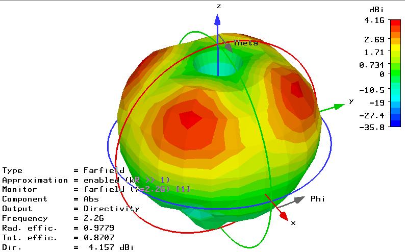
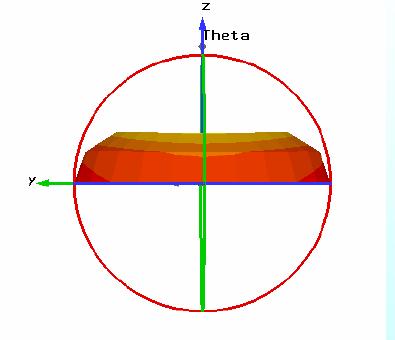
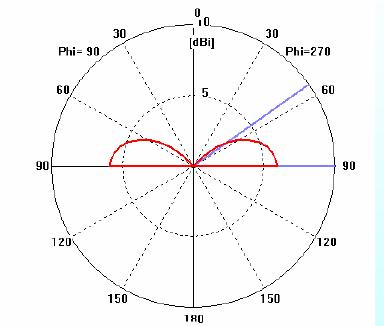
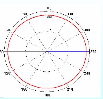
the desired pattern is a monopole-like pattern, with a bi-directional main beam close to the ground plane in the vertical plane and omnidirectional radiation in the horizontal plane, shown as the following:
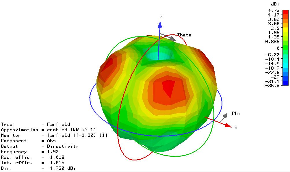
3D pattern:
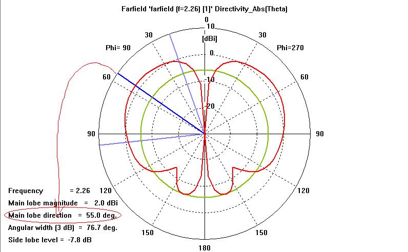
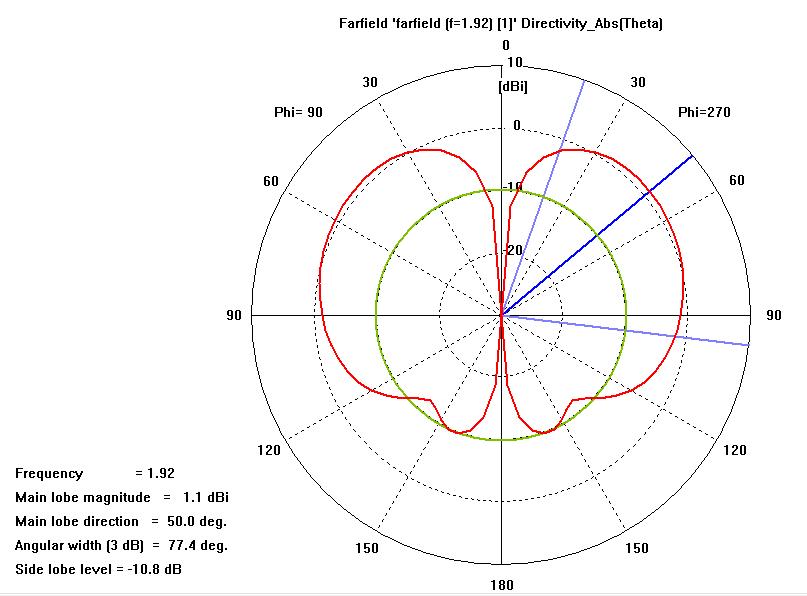
vertical plane:
horizontal plane:
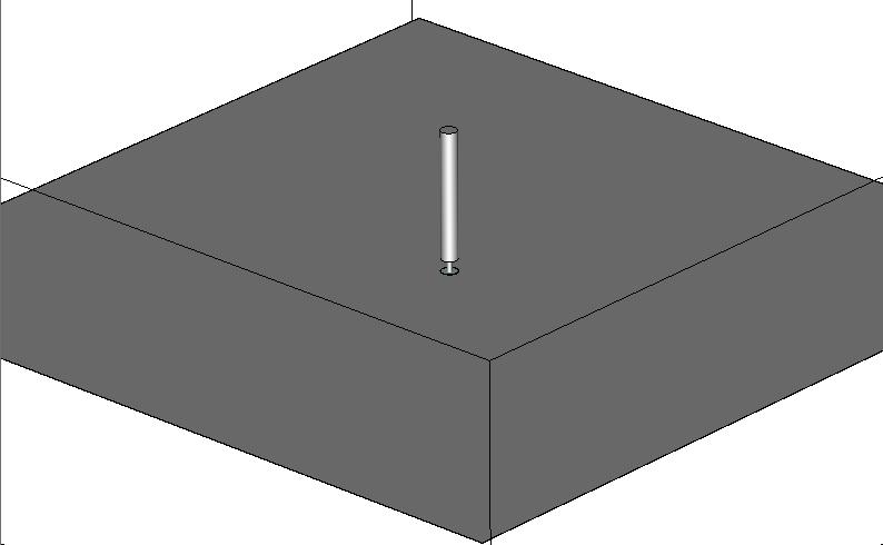
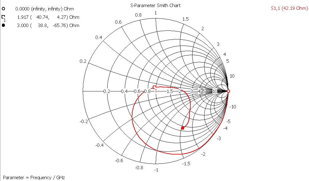
i tried a cone monopole as an initial design:
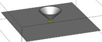
but in the vertical plane, the elevation angle is about 50 degree above the GND. That's too large for me! the closer the main beam is to the GND, the better.
anyone has some suggestions? BTW, there's not much restriction on the bandwidth(it's just OK that the antenna is working at, e.g. 2.4GHz). other antenna type is also acceptable.
many thx!
3D pattern:
vertical plane:
horizontal plane:
i tried a cone monopole as an initial design:
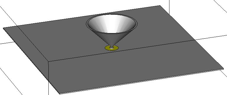
but in the vertical plane, the elevation angle is about 50 degree above the GND. That's too large for me! the closer the main beam is to the GND, the better.
anyone has some suggestions? BTW, there's not much restriction on the bandwidth(it's just OK that the antenna is working at, e.g. 2.4GHz). other antenna type is also acceptable.
many thx!