Continue to Site

Welcome to EDAboard.com

Welcome to our site! EDAboard.com is an international Electronics Discussion Forum focused on EDA software, circuits, schematics, books, theory, papers, asic, pld, 8051, DSP, Network, RF, Analog Design, PCB, Service Manuals... and a whole lot more! To participate you need to register. Registration is free. Click here to register now.

Another OpAmp Basic Question

Status
Not open for further replies.

~analoger~

Banned
Member level 1
Joined
Jan 4, 2013
Messages
37
Helped
1
Reputation
2
Reaction score
1
Trophy points
1,288
Location
Mars
Visit site
Activity points
0
For an ideal OpAmp, is it always the case that the voltage of the inverting input follows the voltage of the noninverting input and not the other way around? And probably this is what distinguishes both inputs when doing analysis regardless of current direction and voltage polarity assumptions.

Thanks.
 

I read that rule in Sergio Franco's "Design with OpAmps and Analog ICs" that in ideal case and in linear region the (-) follows the (+) voltage.
 
  • Like
Reactions: FvM

    FvM

    Points: 2
    Helpful Answer Positive Rating
Well, an ideal op-amp has gain of infinity. However, practical ones have just a very high gain (the so-called open-loop gain may be approx. magnitude of 100 000), but for most situations they still behave close to the ideal one.

As chuckey pointed out, that high gain causes the output of amplifier to go to the maximum/minimum if difference in voltage between + and - input is larger than some microvolts.

One uses seldom op-amps without any negative feedback, except maybe as comparators, which then have outputs going between extreme + and extreme - depending which way the input differential voltage happens to be ("which one is higher...")

Typically with negative feedback one limits the gain to much lower than the open-loop value, and in that process causes the (-) input to virtually track the (+) input. That is because the negative feedback feeds the (-) input with a signal, which tries to minimize the input differential voltage between (-) and (+) inputs. That's why you have seen "... the voltage of the inverting input follows the voltage of the non-inverting input" - not other way around, as the NEGATIVE feedback goes by definition from output to the (-) (NEGATIVE) input pin of the op-amp.

There are many good books about op-amps, and I think you should be able to study the basic equations there. Even humble Wikipedia has the basic stuff in an article (https://en.wikipedia.org/wiki/Operational_amplifier).
 

in ideal case and in linear region the (-) follows the (+) voltage
I don't think that it's a correct rule. In general, in OP amplifier circuits the external connected feedback from OP output tries to zero the differential input voltage.

In most OP circuits, a fraction (or all) of the output voltage is feed back to the inverting input. In this (and only in this) case, the inverting (-) input "follows" the noninverting (+) input. But you can also design OP circuits, where the inverted output voltage is feed back to the (+) input, contradicting the suggested "rule".
 
  • Like
Reactions: LvW

    LvW

    Points: 2
    Helpful Answer Positive Rating
Adding to what FvM wrote...
If the opamp is used e.g. as a comparator or Schmitt trigger, then neither of the inputs follows the other input.
 

I'm not sure if the feedback connection is the one that decides on which input follows which. I think the idea is that an OpAmp tries to make the potential difference between the two inputs as minimum as possible by forcing the (-) input to track the (+) inout voltage, and not the opposite, so that inversion and negative feedback works. This is my understanding...

There are many good books about op-amps, and I think you should be able to study the basic equations there. Even humble Wikipedia has the basic stuff in an article (https://en.wikipedia.org/wiki/Operational_amplifier).

Not exactly. The many books except the one I mentioned just repeat the same story and the same famous configurations and their analysis. Unfortunately not a single book states it clearly how input signs affect the analysis.
 

May I add my view?
I dislike all formulations like "one input follows the other one". I think, such a view does not help too much because it is not correct.
In fact, the situation is as follows:
As long as the opamp (with negative feedback) is within its linear amplification range the voltage difference between the opamp`s positive and the negative input terminal
is always Vp-Vn=Vd=Vout/Ao with Ao=open-loop gain.
This formula applies, of course, for inverting and non-inverting operation of the amplifier.
In particular, for inverting operation the non-inv. input is grounded and the voltage at the inv. terminal never "follows" this zero potential.
Instead, according to the relation given above this voltage is Vn=-Vout/Ao and, thus, strictly follows Vout.
 
Actually, if you think about the CMOS amplifier, the ground does not always mean the zero potential otherwise common mode voltage. In that case what do you want to say?
 

I'm not sure if the feedback connection is the one that decides on which input follows which.

Sergio Franco seems to be sure, however:
The op amp controls vn via the external feedback network. Without feedback, the op amp would be unable to inflence vn.
As mentioned in post #6.

Quite obviously, the author doesn't want to formulate a rule about OPs. He tries a visual explanation of a common OP circuit., with some prerequisites like feedback to vn.

If you don't mind the bad facsimili quality, check the original text at page 13


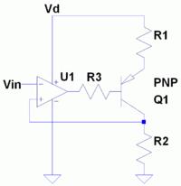
P.S.: To illustrate my previous comment that negative feedback must not necessarily go to vn, a circuit where "vp follows vn".

 
Last edited:

I still have problem figuring out what makes (-) and (+) inputs different in analysis of the ideal OpAmp circuit. Do the input signs represent the voltage polarity across the infinite input resistance?
 

A + signal going in to a + input makes the output go +, a + signal going into a - input makes the output go -. Note these are the SIGNAL voltages, both the inputs may be a some + (or-) fixed bias, but if they are equal then the output will also be at 0V.
farnk
 

Status
Not open for further replies.

Similar threads

Part and Inventory Search

Welcome to EDABoard.com

Sponsor

Back
Top