Continue to Site

Welcome to EDAboard.com

Welcome to our site! EDAboard.com is an international Electronics Discussion Forum focused on EDA software, circuits, schematics, books, theory, papers, asic, pld, 8051, DSP, Network, RF, Analog Design, PCB, Service Manuals... and a whole lot more! To participate you need to register. Registration is free. Click here to register now.

another op amp question, this time about supply levels and amp performance

Status
Not open for further replies.

obrien135

Full Member level 5
Joined
Nov 10, 2009
Messages
240
Helped
5
Reputation
10
Reaction score
5
Trophy points
1,298
Location
Connecticut
Activity points
3,259
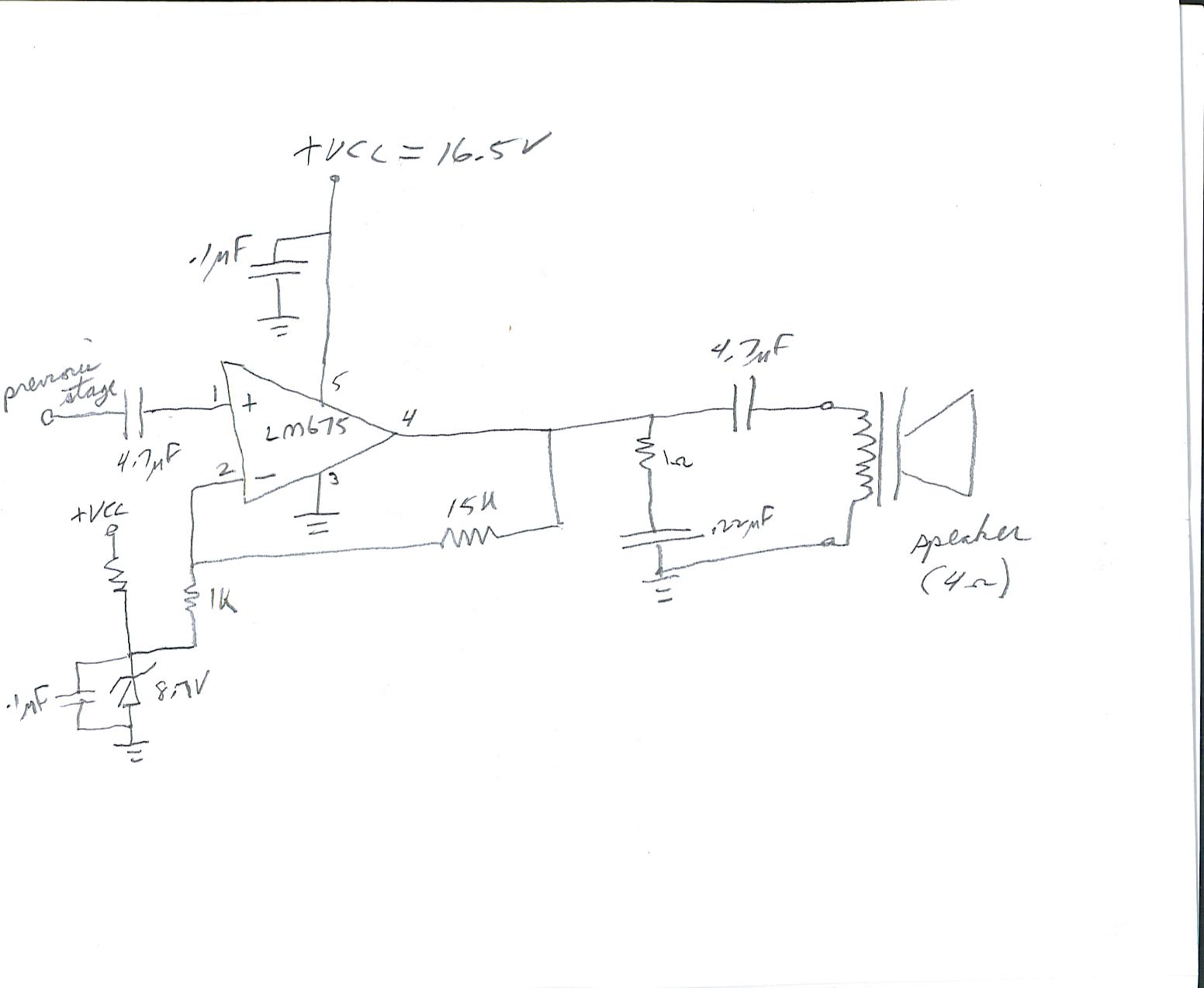
I built an op amp circuit with an LM675 op amp. The supply was supposed to be 17 volts from plus rail to minus rail. But it ended up being about 16.5 VDC. The circuit common or "ground" midway between the rails (it's a single supply circuit) was implemented with a zener diode. The closest I could get to 8.5 volts was 8.7V and it ended up reading about 8.9 or 9.0 V. The op amp output seems to be stuck at around minus rail. Is this due to the offset caused by the uneven supplies, or simply not enough supply voltage? The minimum supply voltage for the LM675 is 16V. I am using a non-inverting configuration.
 

What about posting your schematics?

But if you're sure your wiring is correct you might try another opamp of same type.
 
**broken link removed**

The typical applications figure in the above link shows the circuit. Just add an 8.7Vzener from the 1kohm to minus supply and a 360 ohm resister from 1kohm to plus supply. Minus supply is really ground. It is a single supply circuit. The supply is about 16.5VDC. I don't have the equipment to draw or scan the picture, so I hope this helps.
 

I attached the file that contains the schematic mentioned above. I noticed that I didn't put in the 22kohm resister from the + input to ground either. What kind of trouble could that cause?
 

Attachments

  • LM675.pdf
    175.3 KB · Views: 109

It depends on your signal source. Is it AC or DC coupled? If DC, is it relative to ground or the zener? You would need to connect the 22k to the zener, not ground. The same applies to the 1k shown to ground on page 1.

Keith.
 
To supply the input bias current if it is AC coupled and also to provide a DC reference. As stated earlier, it would be easier is you posted a diagram. We still don't know if you are AC coupling or where you have connected the 1k resistor to the inverting input to.

Keith.
 
Yes, that is how I did it, but the 22kohm resister is not included. The schematic I based it on only showed a 22k going to the circuit common midway between the plus and minus supplies which I implemented with a zener diode circuit. I will try drawing a picture by hand and scanning it. I got the scanner working. Maybe that will help.
 

There are plenty of free packages to draw a schematic such as Eagle . Did you include the capacitor drawn from the 1k to ground by FvM?

Keith.
 

Simply consider, that the voltage at the positive input sets the output bias, either with a gain of 21, as in the original circuit, or with a gain of 1, due to the AC coupling in my example.

I understood, that your circuit is different, but because the input bias is unclear, I suggested my variant instead.
 
I reopened the thread, because there is still a little bit more I would like to learn, if someone knows the answer. I am going to try thr 22kohm resister today if I can get up to the other end of the state where the circuit is. there was some snow last night but it wasn't too bad. The question is. With an LM675 op amp, if I use +/- 8.25 volt supplies, will that be too close to the minumun suppply voltage for it to work? Especially if the zener circuit that creates the circuit common forr the 1k and 22k resisters is all little off (about 500mV)? And also, if this does create a problem, is this due to the offset this causes in the biasing, or is it due to one of the supplies being below the minimum, or both of those reasons?

Thank you,

George

P.S. I was thinking of purchasing a larger transformer, to get a higher supply or at least the 17V that I originally designed for before I chinced out and bought a slighhtly lower one at radio Shack.
 
Last edited:

If you look to the datasheet, you'll notice that the specified voltage range goes down to about +/- 6V. Of course the available output is reduced. Also baising the about different from mid-supply shouldn't have other consequences except reducing the undistorted output power.

I previously wanted to mention, that an output capacitor of 4.7 uF creates a low frequency cut-off at about 8.5 kHz, most likely unwanted for an audio application.
 

You were shown how to make the amplifier in post #8 so why don't you do it like that?? The 22k resistors must have the same values and can be anything from 10k to 100k. They set the idling output DC voltage. The 1k resistor has a capacitor to ground, not a zener diode.
 

Status
Not open for further replies.

Similar threads

Part and Inventory Search

Welcome to EDABoard.com

Sponsor

Back
Top