Continue to Site

Welcome to EDAboard.com

Welcome to our site! EDAboard.com is an international Electronics Discussion Forum focused on EDA software, circuits, schematics, books, theory, papers, asic, pld, 8051, DSP, Network, RF, Analog Design, PCB, Service Manuals... and a whole lot more! To participate you need to register. Registration is free. Click here to register now.

Anomali with 7486 logic IC

Status
Not open for further replies.

huys cobb

Member level 3
Joined
Nov 10, 2006
Messages
60
Helped
2
Reputation
4
Reaction score
1
Trophy points
1,288
Activity points
1,614
Hai

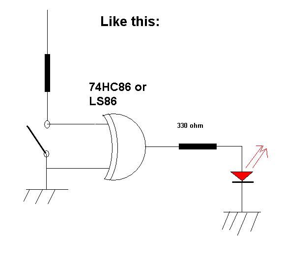
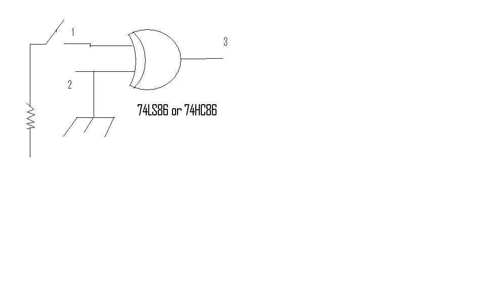
AFter test this circuit:

33_1207200986.jpg


the result between the 74ls86 and 74hc86 very different..

each time I press the button..the 74LS86 didn't change the status ouput while the 74hc86 basically from botton input..
the all of 74LS86s was new.


[/img]
 

1. HC IC with open input has unpredictable behaviour.
2. The "circuit" itself isn't fully clear. Where do you connect the resistor?
 

Thank's

>1. HC IC with open input has unpredictable behaviour.
The 74HC86 result..similiar with the system...
The 74LS86 always on(1) at the output..

>2. The "circuit" itself isn't fully clear. Where do you connect the resistor?
Do I need the resistor at the output..?for 74LS86. to get similiar result with 74HC86..?

THank you
Huys Cobb
 

This points are unclear with your posted circuit:
38_1207287398.gif


Whatever is wrong here, I suggest to try this version:

52_1207287508.gif
 

The circuit just like that...take look at the attachment...

cause .avi couldn't upload..zipped the video.

Is there any modification to made the 74LS86 works like 74HC86..?
Must I added resistor at output to get similair result with HC86?

Thank's a lot
Huys Cobb
 

When you say, your circuit is "like that", altough you have drawn a completely different circuit, I wonder what's the actual circuit of your breadboard. Unfortunately, I can't see it from your nice video. Also I don't know, how you connected the LED's.
 

One of the main differencies between LS and HC series is it's input gate current. At LS this current is tipically -1mA, while at HC it is in range of -1µA for logic 0. A resistor on the input must be small enough to allow, when grounded on the other end, the input gate voltage is below logic 0 level. With LS series this resistor must be smaller than approx. 500Ω.
Take a look at datasheets for this two type of gates to verify this. Check allso voltage s for logic levels for both series.
 

Thank you very much for your information

>When you say, your circuit is "like that", altough you have drawn a completely >different circuit, I wonder what's the actual circuit of your breadboard. >Unfortunately,
>I can't see it from your nice video. Also I don't know, how you connected the >LED's.

Like this


>One of the main differencies between LS and HC series is it's input gate current. >At LS this current is tipically -1mA, while at HC it is in range of -1µA for logic 0.

I Agree.....

>resistor on the input must be small enough to allow, when grounded on the other >end, the input gate voltage is below logic 0 level. With LS series this resistor must >be smaller than approx. 500Ω.
>Take a look at datasheets for this two type of gates to verify this. Check allso >voltage s for logic levels for both series.

I'll check with VOM the circuit like .avi.

Last question...

Is the circuit in the real world similar when I implemented..The different only
..basically from datasheet only..?

Thank you very much
Huys Cobb
 

The circuit, as shown, can be expected to work with LS and HC family, although LED intensity may be different. If it's not operating at all, a defective device or a wiring error is likely the reason.
 

Thank you very much
FVM

Still have similiar result...
I'll sent you my expierienced next...
Lot of ICs 74HC86 and LS86 had different result...
all brand new..

Thank you
Huys Cobb
 

LS chips were derived from the original TTL circuits. Even though it is very bad practice, TTL and LS have a "feature" - if an input is left floating, it appears as a logic 1. That is, unused inputs float high. This is not true with CMOS parts, even TTL equivalent CMOS parts like the ACT or HCT series. With all CMOS parts, every input pin must have a path to a voltage, either VDD, GND, or an input signal. The path can be a direct connection or through a resistor, but it must be there for stable operation.

ak
 

Status
Not open for further replies.

Part and Inventory Search

Welcome to EDABoard.com

Sponsor

Back
Top